
Building material surface coating equipment

A building material surface and coating technology, applied in related fields, can solve the problems of uneven surface and time-wasting of building material spraying, and achieve the effect of rapid polishing

Active Publication Date: 2020-04-10
湖南中环高新材料技术有限公司
View PDF5 Cites 14 Cited by
  • Summary
  • Abstract
  • Description
  • Claims
  • Application Information

AI Technical Summary

Problems solved by technology

[0003] When spraying building materials, since there are often bumps on the surface of building materials, when spraying, it is often necessary to write the building materials first for grinding, and then spray after grinding, which will waste a lot of time. The existing coating equipment on the surface of building materials It is not easy to quickly polish the surface of building materials, resulting in uneven sprayed surfaces of building materials

Method used


Image

  • Building material surface coating equipment
  • Building material surface coating equipment
  • Building material surface coating equipment

Examples


Embodiment 1

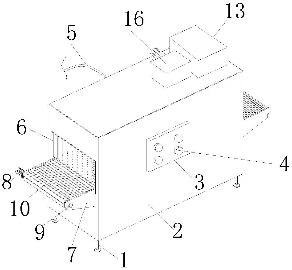
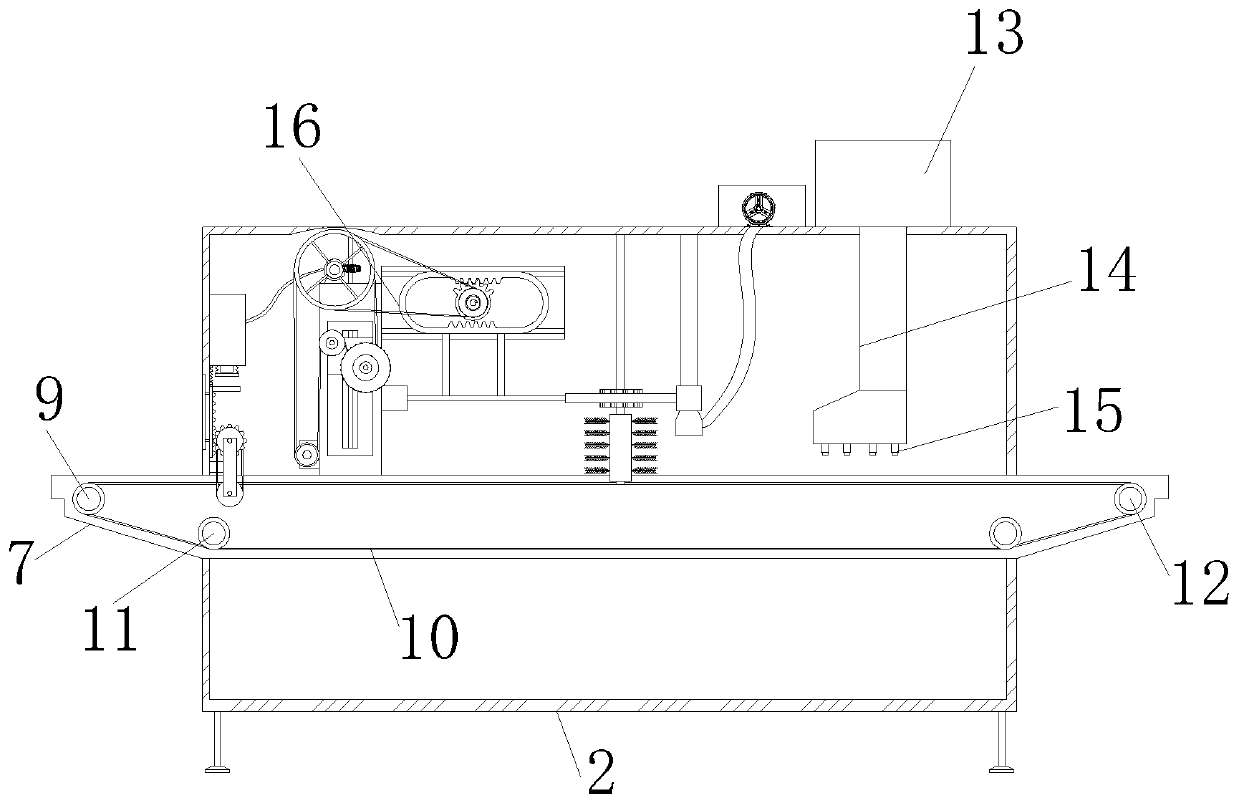
[0036] The present invention provides a coating device for the surface of building materials through improvement, including a support foot 1, a conduit 14, a spray nozzle 15 and a polishing and cleaning device 16. The support foot 1 is fixedly connected to the four corners of the bottom of the frame body 2, and the right end of the frame body 2 is provided with a Control panel 3, button 4 is installed on the front end of control panel 3, power wire 5 is fixed on the rear end of frame body 2, protective strips 6 are equidistantly distributed at the middle opening of the front end of frame body 2, and bolts at the front and rear ends of frame body 2 and support plate 7 Connection, the support plate 7 is locked and fixed with the front end of the first motor 8 by screws, the output end of the first motor 8 is connected to the middle of the driving roller 9 in rotation, and the driving roller 9 is connected to the inner side wall of the directional wheel 11 and the driven roller 12 ...

Embodiment 2

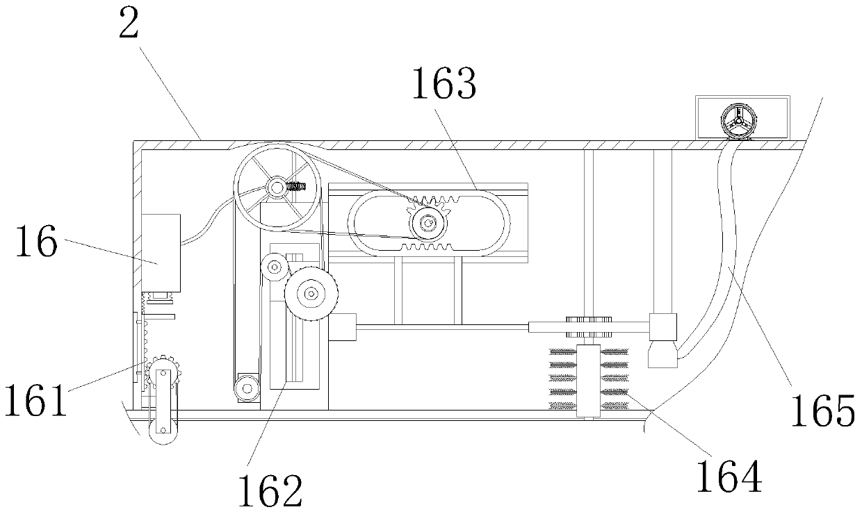
[0049] The present invention provides a coating device for the surface of building materials through improvement, the second pulley 1627 and the third pulley 1628 have the same size, and the second pulley 1627 and the third pulley 1628 are along the upper left side and the lower right end of the front end of the sliding plate 1629 The lower end of the guide frame 1634 is provided with a chute 1639, the receiving rod 1635 slides along the inner wall of the chute 1639, and the upper and lower sides of the track frame 1633 are provided with tooth angles 16310, and the tooth angles 16310 are equidistantly distributed along the upper and lower sides of the track frame 1633, and the section of the front end of the suction head 1653 is trapezoidal.

[0050] The present invention provides a kind of coating equipment of building material surface through improvement, and its working principle is as follows;

[0051] First, before use, place the coating equipment on the surface of the bu...


PUM


Abstract

The invention discloses building material surface coating equipment, which comprises a polishing and cleaning device, wherein the polishing and cleaning device comprises a polishing mechanism arrangedin a frame body; a second motor drives a driving belt pulley to rotate by means of a worm, so that the driving belt pulley drives a first belt pulley, a second belt pulley and a third belt pulley torotate by means of a second transmission belt; the third belt pulley further drives a polishing roller to rotate; a worm rotates to drive a worm wheel to rotate, so that the worm wheel drives a sliding plate to move towards the lower end by means of a ball screw, the polishing roller grinds the surface of a building material downwards, and the beneficial effect of polishing the surface of the building material can be quickly achieved; and a dust suction mechanism is arranged in the frame body, an exhaust fan is powered on to operate, the kinetic energy of a gas is improved by means of mechanical energy, and therefore a suction gas is generated, a gas suction head sucks dust to the inner side of the collecting frame to be collected by using a gas suction pipe, and the beneficial effect thatthe dust can be quickly sucked is achieved.

Description

technical field [0001] The invention relates to related fields, in particular to a coating device for the surface of building materials. Background technique [0002] Building materials include wood, bamboo, stone, cement, concrete, metal, brick, ceramics, glass, engineering plastics and composite materials used in civil engineering and construction engineering. With the development of society, the decoration of building materials The effect can no longer meet the needs of human life. For this reason, engineers have coated various coating materials with special decorative effects and functions on the surface of building materials to make them better thermal insulation, heat resistance, durability and Beautiful and other special effects. [0003] When spraying building materials, since there are often bumps on the surface of building materials, when spraying, it is often necessary to write the building materials first for grinding, and then spray after grinding, which will w...

Claims


Application Information

Patent Timeline
Patent Type & Authority Applications(China)
IPC IPC(8): B05B16/20B05B16/60B08B1/00B08B1/04B08B5/04B08B15/04B24B27/00
CPCB05B16/20B05B16/60B24B27/00B08B5/04B08B15/04B08B1/12B08B1/32
Inventor 李怡东
Owner 湖南中环高新材料技术有限公司
Learn More