Winding machine with feeding function

A winding machine and functional technology, applied in the field of winding machines with feeding function, can solve the problems of inconvenient discharge, low production efficiency, unfavorable market competitiveness, etc., to save time, improve efficiency, and facilitate feeding Effect

Pending Publication Date: 2020-04-10
义乌市申凯线业有限公司
View PDF0 Cites 0 Cited by
  • Summary
  • Abstract
  • Description
  • Claims
  • Application Information

AI Technical Summary

Problems solved by technology

In the specific operation process, it is necessary to manually place the workpieces (frames to be wound) on the jig one by one, resulting in low production e

Method used


Image

  • Winding machine with feeding function
  • Winding machine with feeding function
  • Winding machine with feeding function

Examples


Embodiment 1

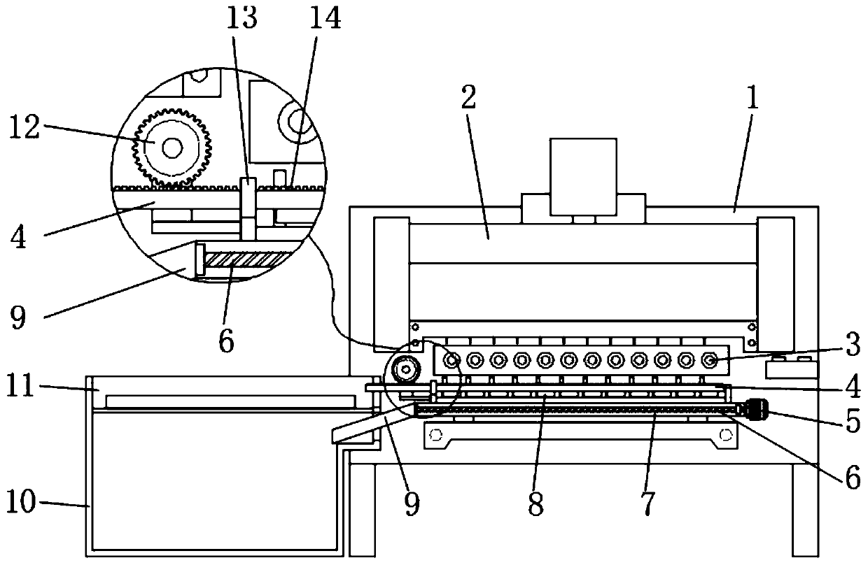
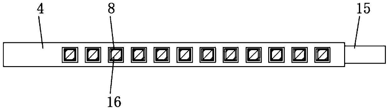
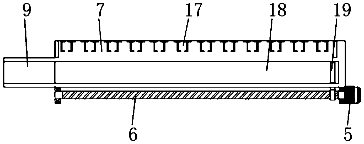
[0030] Embodiment one, with reference to Figure 1-3 , a winding machine with a feeding function, comprising a winding machine body 1, a winding frame 2 is arranged on the front surface of the winding machine body 1, and a plurality of winding shafts 3 are installed rotating below the winding frame 2, The bottom of the winding shaft 3 is provided with an unloading frame 7, and one side surface of the unloading frame 7 is provided with a discharge channel 18, and one side of the discharge channel 18 is located at the edge of the surface of the discharge frame 7 and is equidistantly provided with a plurality of feeding Groove 17, and the top of a plurality of feeding troughs 17 is set up with loading rack 4, and one end of unloading rack 7 is welded with baffle plate, and the surface of baffle plate is welded with sleeve column 15, and one end of sleeve column 15 is inserted and installed in the feeding Inside the rack 4, the other end of the unloading rack 7 is welded with a sl...

Embodiment 2

[0031] Embodiment two, refer to figure 1 , image 3 and Figure 5A discharge motor 5 is installed on the side of the unloading frame 7, and the output end of the discharge motor 5 is connected to a screw mandrel 6 in rotation, and one end of the screw mandrel 6 is fixedly connected with the side of the unloading frame 7 through a bearing seat, and the screw mandrel 6 The surface of the surface is threadedly connected with a threaded sleeve 22, and one end of the threaded sleeve 22 is welded with a connecting rod, and one end of the connecting rod runs through the unloading rack 7 and is fixedly connected with a scraper 19, and the scraper 19 is in the discharge channel 18 of the unloading rack 7 Inside, a control panel is installed on the surface of the winding machine body 1, and the output end of the control panel is electrically connected to the discharge motor 5, and one side of the screw rod 6 is located on the side of the unloading frame 7, and a strip-shaped relief slo...

Embodiment 3

[0032] Embodiment three, refer to figure 1 and Figure 4 , the top surface of the material box 10 is located on both sides of the suction channel 11, and there are material guide chambers 20, and the bottom surface of the material guide chamber 20 is an inclined slope, and the inner walls of the two material guide chambers 20 pass through the suction channel 11 A through groove 21 with a rectangular structure is provided. The inside of the feed box 10 is located below the material suction channel 11 and is provided with a collection cavity. The side wall surface of the feed box 10 is provided with a rectangular slot corresponding to the collection cavity. Corresponding to the material plate 9, one end of the material discharge plate 9 extends through the rectangular groove into the material collection chamber of the material box 10, the material discharge plate 9 is placed obliquely with respect to the unloading frame 7, and the material discharge plate 9 welded obliquely is c...


PUM


Abstract

The invention discloses a winding machine with a feeding function. The winding machine comprises a winding machine body, wherein a winding frame is arranged on the surface of the front end of the winding machine body, a plurality of winding shafts are rotationally installed below the winding frame, and a discharging frame is arranged below the winding shafts. According to the winding machine, a motor for driving a gear is connected with a control unit of the winding machine body, when the discharging frame finishes discharging, the control unit starts the motor and an electromagnet in a material attraction cavity to enable the output end of the motor to drive the gear to rotate, so that the gear drives a feeding frame to slide through a rack until the material attraction cavity of the feeding frame is located above a material attraction channel of a material box, the electromagnet is promoted to attract the metal end of a high-pressure pack, so that the high-pressure pack is embedded into the material attraction cavity; then the motor is reversely rotated, the gear is promoted to drive the feeding frame to reset, then the electromagnet is closed, and the high-pressure pack falls into a feeding groove of the discharging frame; and automatic feeding is achieved, the manual feeding time is saved, so that the efficiency of the winding machine is improved.

Description

technical field [0001] The invention relates to the technical field of winding machines, in particular to a winding machine with a feeding function. Background technique [0002] A winding machine is a device that winds a linear object onto a specific workpiece. Most of the wires wound by a winding machine are enamelled copper wires (inductance coils for electronic and electrical products), enamelled aluminum wires, textile Threads (yarns and coils for winding textile machines), as well as heating wires and soldering wires, wires, cables, etc. for winding electric heating appliances. [0003] High-voltage package, the correct name is line output transformer, also known as line package or line transformer. The working principle of the high-voltage package of the display is basically the same as that of the TV. Its main function is to generate anode high voltage. Voltage, the production process usually requires a winding machine for winding processing. [0004] When the wind...

Claims


Application Information

Patent Timeline
IPC IPC(8): B65G47/92B65H67/04
CPCB65G47/92B65H67/0411B65H67/0417
Inventor 杨兴武任大龙王起
Owner 义乌市申凯线业有限公司
Why Eureka
Try Eureka