A heat treatment device for the production of machine tool rotary shafts

A heat treatment device and rotary shaft technology, applied in heat treatment furnaces, heat treatment equipment, quenching devices, etc., can solve the problems of inability to collect slag, waste of resources, etc., achieve good cooling, realize recycling, and improve the effect of quenching quality

Active Publication Date: 2021-03-30
江苏伯能机床制造有限公司
View PDF2 Cites 0 Cited by
  • Summary
  • Abstract
  • Description
  • Claims
  • Application Information

AI Technical Summary

Problems solved by technology

A heat treatment device for the production of machine tool rotary shafts in the above-mentioned patent has the following disadvantages: when the device performs quenching work on the rotary shaft, it cannot collect the slag generated during the heat treatment process of the rotary shaft, resulting in a waste of resources

Method used


Image

  • A heat treatment device for the production of machine tool rotary shafts
  • A heat treatment device for the production of machine tool rotary shafts
  • A heat treatment device for the production of machine tool rotary shafts

Examples


Embodiment 1

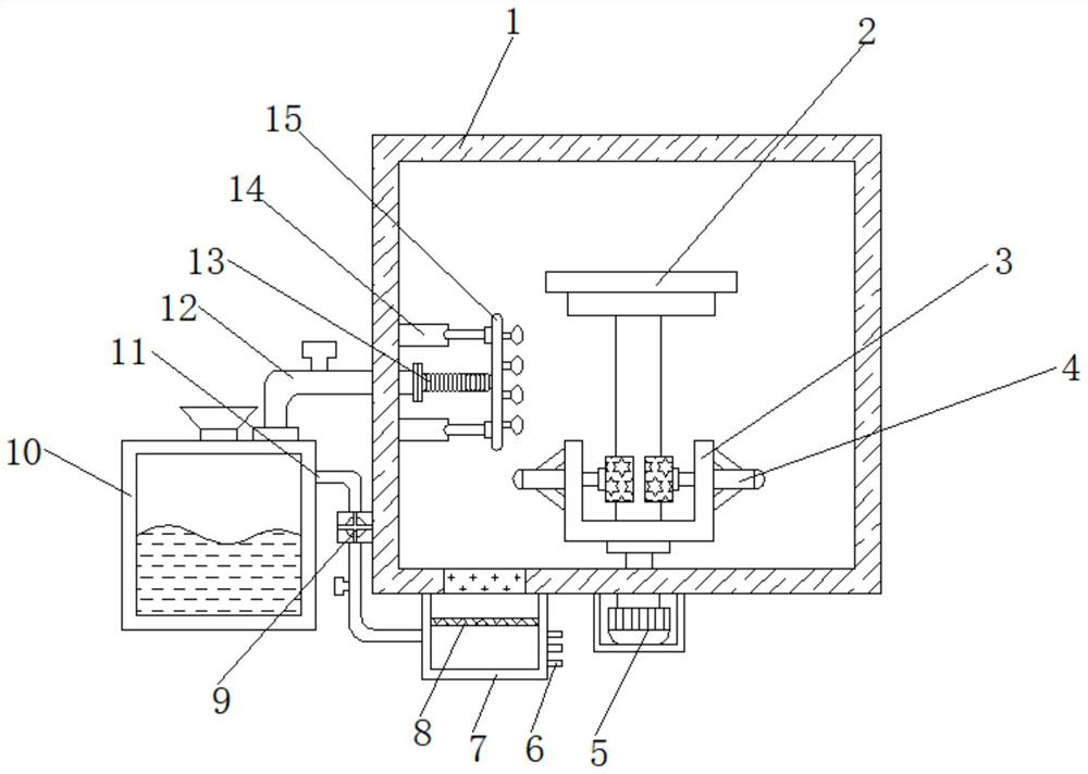
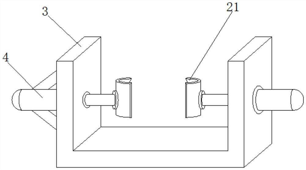
[0026] refer to Figure 1-2 , a heat treatment device for the production of machine tool rotary shafts, comprising a quenching box 1 and a liquid storage box 10, the bottom outer wall of the quenching box 1 is connected to an organic casing by bolts, and a motor 5 is connected to the bottom inner wall of the casing by bolts, and the output of the motor 5 is The outer wall of one end of the shaft is connected with a fixed frame 3 by bolts, and the outer walls of both sides of the fixed frame 3 are connected with a first electric push rod 4 by bolts, and the outer wall of one end of the first electric push rod 4 is connected with a clamping ring 21 by bolts, and The inner wall of one side of the clamping ring 21 clamps the rotary shaft body 2, the top outer wall of the liquid storage tank 10 is plugged with a liquid outlet pipe 12, and the inner wall of one end of the liquid outlet pipe 12 is inserted with a bellows 13, and the bellows 13 A nozzle 15 is plugged into one end, and...

Embodiment 2

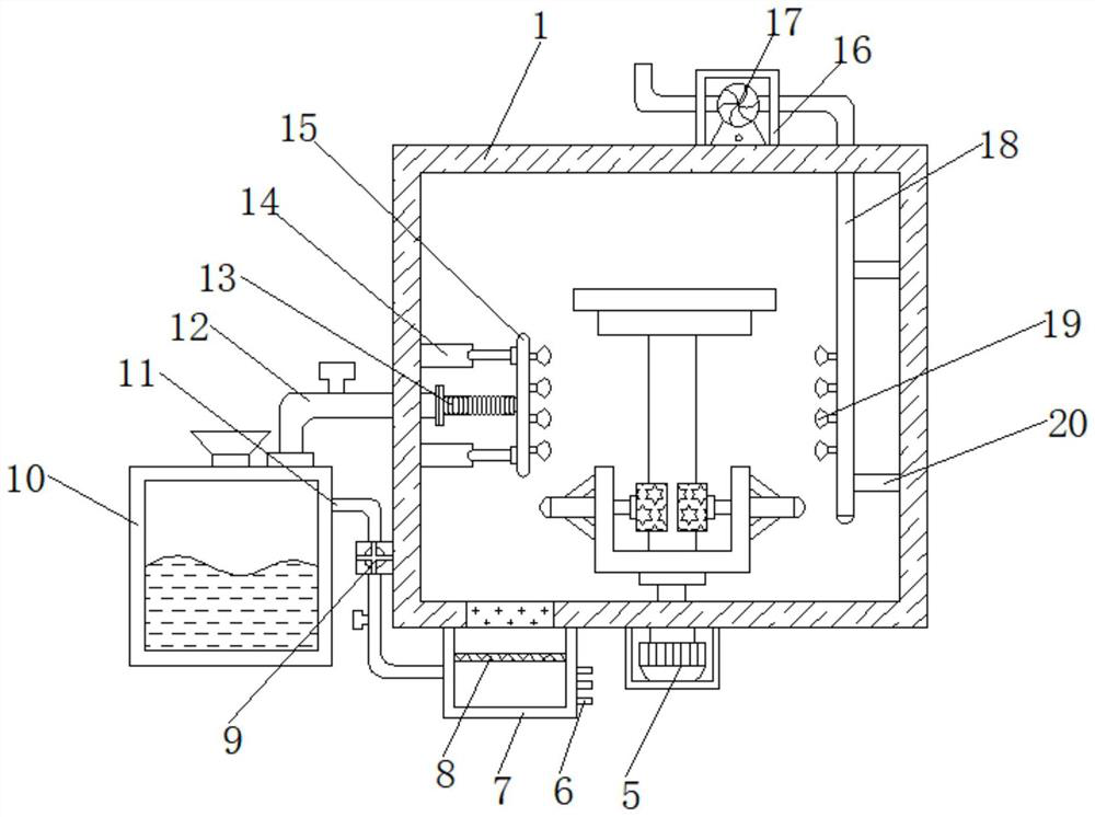
[0030] refer to image 3 , a heat treatment device for the production of machine tool rotary shafts. Compared with Embodiment 1, the top outer wall of the quenching box 1 is connected with a protective shell 16 by bolts, and the bottom inner wall of the protective shell 16 is connected with a blower 17 by bolts. One side outer wall of 17 is plugged with air outlet pipe 18, and one side outer wall of air outlet pipe 18 is plugged with equidistantly distributed air outlet buckets 19, and one side outer wall of air outlet pipe 18 is welded with reinforcing bar 20, and reinforcing bar One end of 20 is welded on one side inner wall of quenching box 1.

[0031]Working principle: When in use, place it on the bottom of the fixed frame 3 before the device quenches the rotary shaft body 2, then start the first electric push rod 4, and the first electric push rod 4 drives the clamping ring 21 to return The rotating shaft body 2 is fixed to ensure the stability of the rotating shaft body...


PUM


Abstract

The invention discloses a heat treatment device for production of rotating shafts of a machine tool. The device comprises a quenching box and a liquid storage box, wherein the outer wall of the bottomof the quenching box is provided with a machine shell; the inner wall at the bottom of the machine shell is provided with a motor, and a fixing frame is arranged on the outer wall of one end of an output shaft of the motor; first electric push rods are arranged on the outer walls of the two sides of the fixing frame, clamping rings are arranged on the outer walls of one ends of the first electricpush rods, and rotating shaft bodies are clamped on the inner walls of one sides of the clamping rings; and a liquid outlet pipe is inserted into the outer wall of the top of the liquid storage box,and a corrugated pipe is inserted into the inner wall of one end of the liquid outlet pipe. According to the device, after the rotating shaft bodies are placed in the quenching box, lye can be sprayedto the surfaces of the rotating shaft bodies through a spray head on the outer wall of one side of a spray pipe so that the rotating shafts can be rapidly cooled, and meanwhile, people can adjust thedistance from the spray head to the rotating shaft bodies through stretching of a second electric push rod, so that the rotating shaft bodies are better cooled.

Description

technical field [0001] The invention relates to the technical field of rotary shaft production, in particular to a heat treatment device for the production of rotary shafts of machine tools. Background technique [0002] During the processing of the rotary shaft of the machine tool, heat treatment is required for the rotary shaft of the machine tool. During the heat treatment process of the rotary shaft of the machine tool, the front shaft needs to be placed in the quenching tank for water circulation cooling treatment. The purpose of quenching is to make the supercooled austenite Martensite or bainite is transformed to obtain martensite or bainite structure, and then combined with tempering at different temperatures to greatly improve the rigidity, hardness, wear resistance, fatigue strength and toughness of the rotary shaft, so as to meet Different use requirements for various mechanical parts and tools. [0003] After searching, the Chinese patent application number is C...

Claims


Application Information

Patent Timeline
Patent Type & Authority Patents(China)
IPC IPC(8): C21D1/667C21D9/28
CPCC21D1/667C21D9/0025C21D9/28
Inventor 张海香邹海丰
Owner 江苏伯能机床制造有限公司
Why Eureka
Try Eureka