Mixed-flow pump with clutch protection structure

A protection structure, mixed-flow pump technology, applied in clutches, friction clutches, mechanical drive clutches, etc., can solve problems such as deepening pump damage, motor burnout, waste, etc., to save resources, prevent burnout, and use flexible and convenient effects.

Active Publication Date: 2020-04-10
江苏中苏智能制造有限公司
View PDF7 Cites 4 Cited by
  • Summary
  • Abstract
  • Description
  • Claims
  • Application Information

AI Technical Summary

Problems solved by technology

[0005] Purpose of the invention: The purpose of the present invention is to provide a mixed-flow pump with a clutch protection structure to solve the problem that the impeller of the current mixed-flow pump proposed in the above-mentioned background technology is integrally cast, res

Method used


Image

  • Mixed-flow pump with clutch protection structure
  • Mixed-flow pump with clutch protection structure
  • Mixed-flow pump with clutch protection structure

Examples


Embodiment Construction

[0025] The present invention will be further described below in conjunction with accompanying drawing and embodiment:

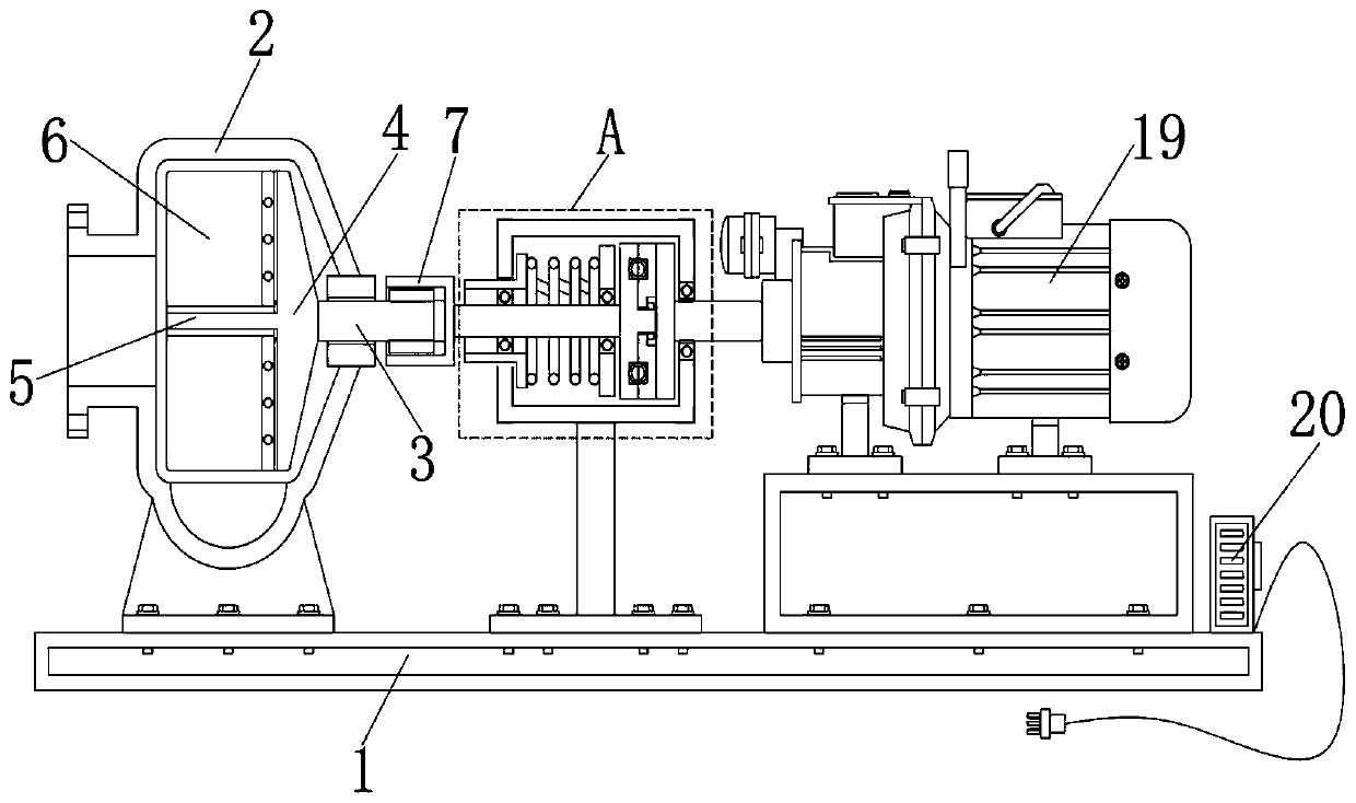
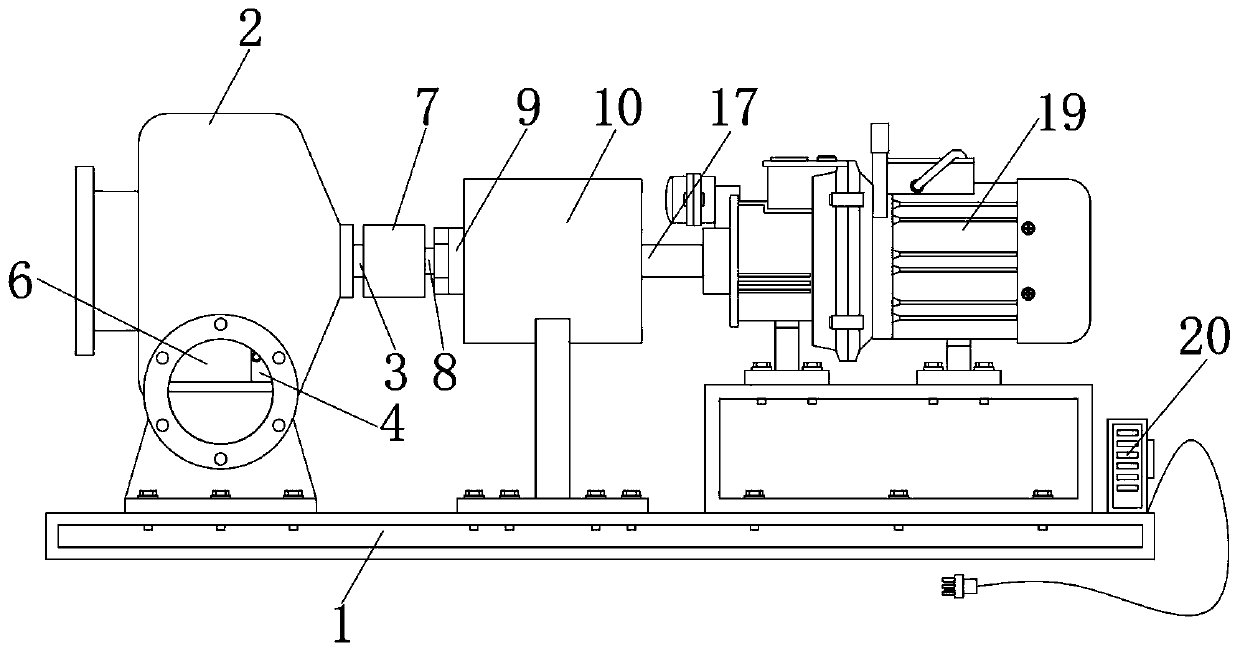
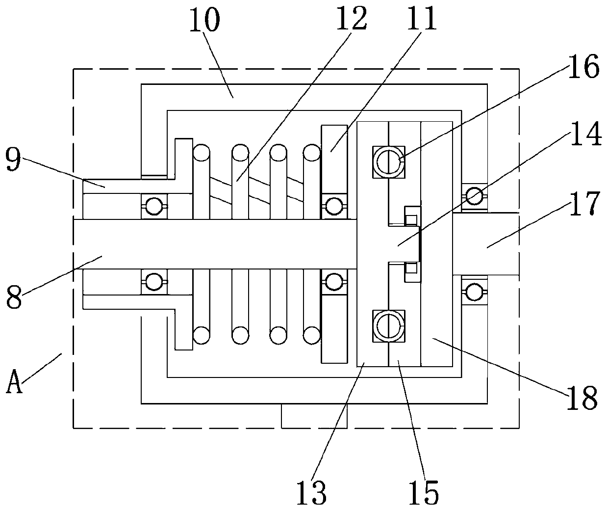
[0026] Such as Figure 1 to Figure 6 As shown, a mixed flow pump with a clutch protection structure of the present invention includes a base 1 and a motor 19, a pump housing 2 is fixed above the base 1, and a rotating shaft 3 is inserted in the middle of the right side of the pump housing 2 One end of the rotating shaft 3 is fixedly welded with an impeller seat 4, and the middle position on the other side of the impeller seat 4 is fixedly welded with an impeller shaft 5, and the outer side of the impeller shaft 5 is evenly inserted with impeller blades 6, and the impeller seat 4 is embedded in the pump casing 2, the impeller seat 4 is rotationally connected with the pump casing 2 through the rotating shaft 3, and a chute is evenly opened on the outer wall of the impeller shaft 5, and a slider is fixedly welded on one end of the impeller blade 6, and the impel...


PUM


Abstract

The invention discloses a mixed-flow pump with a clutch protection structure. The mixed-flow pump with the clutch protection structure comprises a base and a motor; a pump body shell is fixedly installed on the base, a rotation shaft is inserted into the middle of the right side of the pump body shell, an impeller base is fixedly welded to one end of the rotation shaft, an impeller shaft is fixedly welded to the middle of the other side of the impeller base, and impeller blades are evenly inserted into the outer side of the impeller shaft; and the outer side of the other end of the rotation shaft is sleeved with a connecting sleeve, a first transmission shaft is fixedly welded to the other end of the connecting sleeve, an adjusting sleeve is fixed to the outer side of the first transmission shaft through a bearing, and the outer side of the adjusting sleeve is sleeved with a clutch shell. According to the mixed-flow pump with the clutch protection structure, transmission is achieved through rough friction connection between a friction disc and a drive disc, when the interior of the pump body shell is jammed, the drive disc can overcome the friction force at the joint of the drive disc and the friction disc to slowly rotate, the pump body damage degree is effectively reduced, motor burnout is prevented, and the working safety of the device is improved.

Description

technical field [0001] The invention relates to the field of mixed-flow pump equipment, in particular to a mixed-flow pump with a clutch protection structure. Background technique [0002] Mixed flow pump is a kind of pump between centrifugal pump and axial flow pump. When the prime mover drives the impeller to rotate, it acts on the liquid with both centrifugal force and axial thrust. It is a combination of centrifugal pump and axial flow pump. Oblique outflow impeller, which is mainly used to convey clean and polluted media, chemically neutral or aggressive media. [0003] Most of the impellers of existing mixed flow pumps are integrally cast, and the impellers are installed inside the pump casing. If a single impeller blade is accidentally damaged, the entire impeller needs to be replaced, which greatly reduces the maintenance cost of the mixed flow pump and leads to waste of resources; [0004] In addition, the power transmission device of the existing mixed-flow pump i...

Claims


Application Information

Patent Timeline
IPC IPC(8): F04D29/18F04D29/20F04D29/60F04D13/06F04D13/02H02K7/108F16D13/38F16D13/71F16D13/60
CPCF04D13/021F04D13/06F04D29/18F04D29/20F04D29/605F16D13/38F16D13/60F16D13/71H02K7/108
Inventor 宋成法颜爱忠刘冰菁卜亚祥刘金宝
Owner 江苏中苏智能制造有限公司
Why Eureka
Try Eureka