
Variable damping vibration isolator based on ultrasonic motor adjustment

A technology of ultrasonic motor and magnetorheological damper, which is applied in the direction of shock absorbers, shock absorbers, mechanical equipment, etc., and can solve the problem of difficulty in meeting long-life working requirements, inability to maintain the magnetic field of magnetorheological fluid, and reducing liquid damping performance, etc. problems, to achieve the effect of saving energy, reducing energy consumption, and maintaining uniformity

Active Publication Date: 2020-04-10
BEIJING INST OF CONTROL ENG
View PDF8 Cites 4 Cited by
  • Summary
  • Abstract
  • Description
  • Claims
  • Application Information

AI Technical Summary

Problems solved by technology

In view of the fact that there is inevitably a certain gap between the output rod and the sealing cavity, there is inevitably a slight liquid leakage, which not only reduces the liquid damping performance, but also may pollute the environment on the planet, making it difficult to meet the long-life working requirements
[0005] The traditional use of magnetorheological fluid for damping energy consumption mainly uses energized coils to generate a magnetic field, and uses the magnitude of the current to adjust the strength of the magnetic field, thereby changing the dynamic viscosity of the magnetorheological fluid in the orifice and adjusting the damping; when the current in the coil disappears, the magnetic field also disappears, and the magnetic field required by the magnetorheological fluid cannot be maintained, so the coil needs to be powered all the time, so it consumes more power

Method used


Image

  • Variable damping vibration isolator based on ultrasonic motor adjustment
  • Variable damping vibration isolator based on ultrasonic motor adjustment
  • Variable damping vibration isolator based on ultrasonic motor adjustment

Examples


Embodiment Construction

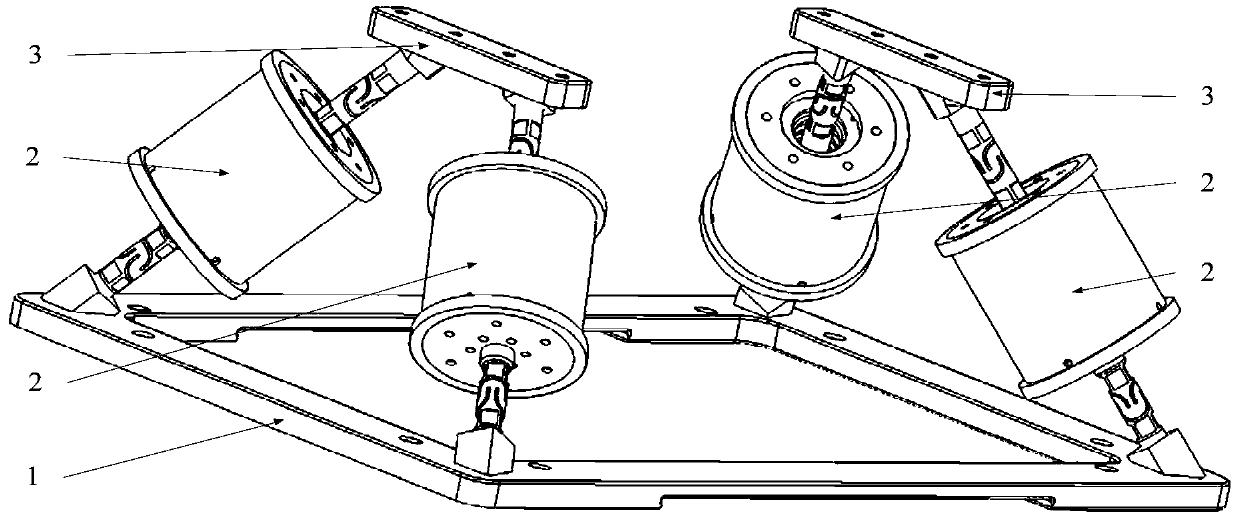
[0029] The vibration isolation effect of a vibration isolator is closely related to its damping. Among them, small damping vibration isolation can effectively isolate high-frequency vibration, while large damping vibration isolation can quickly dissipate vibration energy with large amplitude such as resonance, so it can effectively suppress the control torque. The relatively large vibration generated by inertial actuators such as gyroscopes during maneuvering. Therefore, the present invention proposes a method of using an ultrasonic motor to drive a permanent magnet to rotate, adjust the coincidence degree of the magnetic field and the orifice, and increase the viscosity of the magnetorheological fluid in the orifice entering the magnetic field to greatly increase, thereby realizing the vibration isolator. The variable damping vibration isolation method provides a variable damping vibration isolator based on ultrasonic motor adjustment.

[0030] Such as figure 1 As shown, a v...


PUM


Abstract

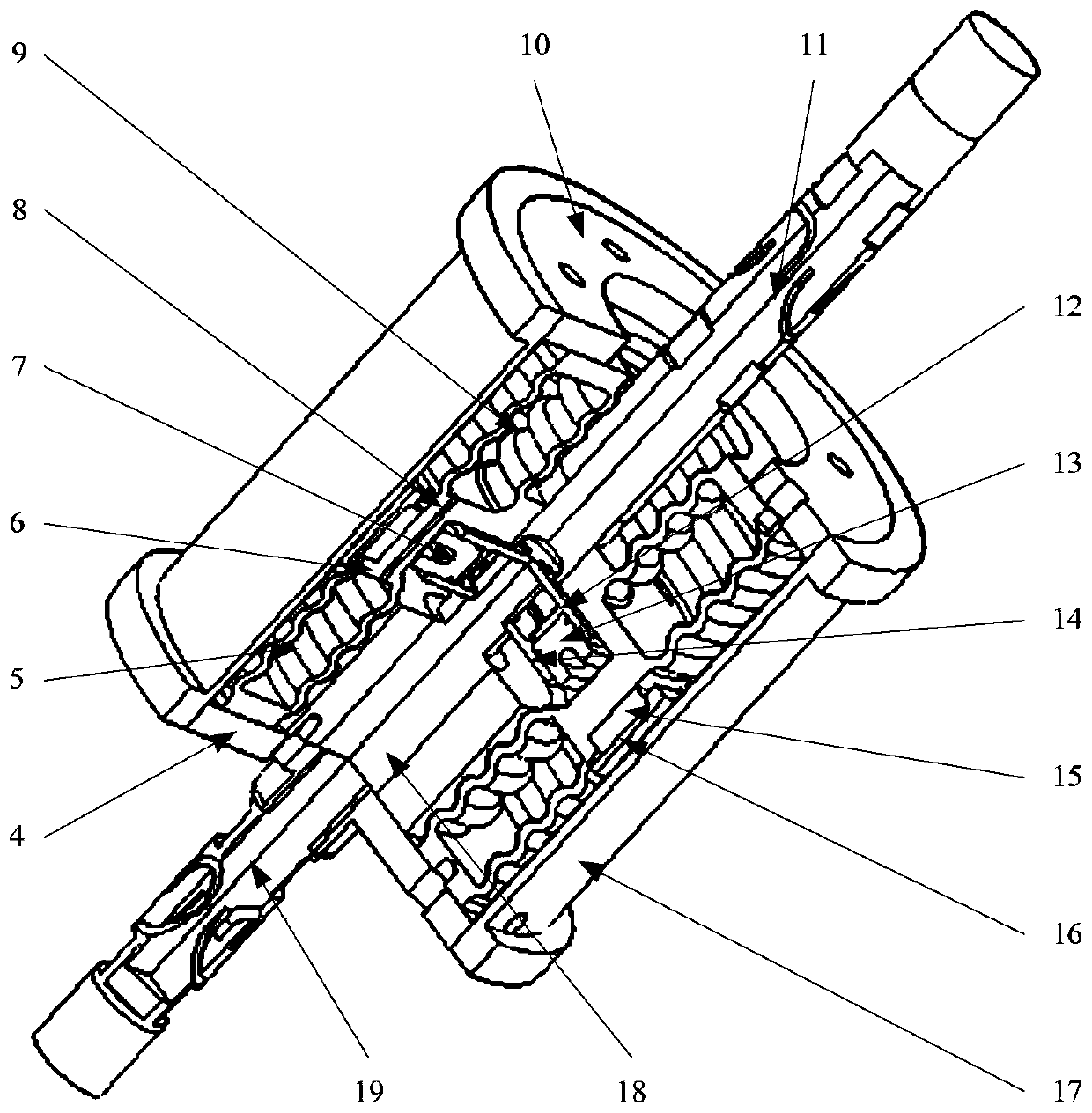
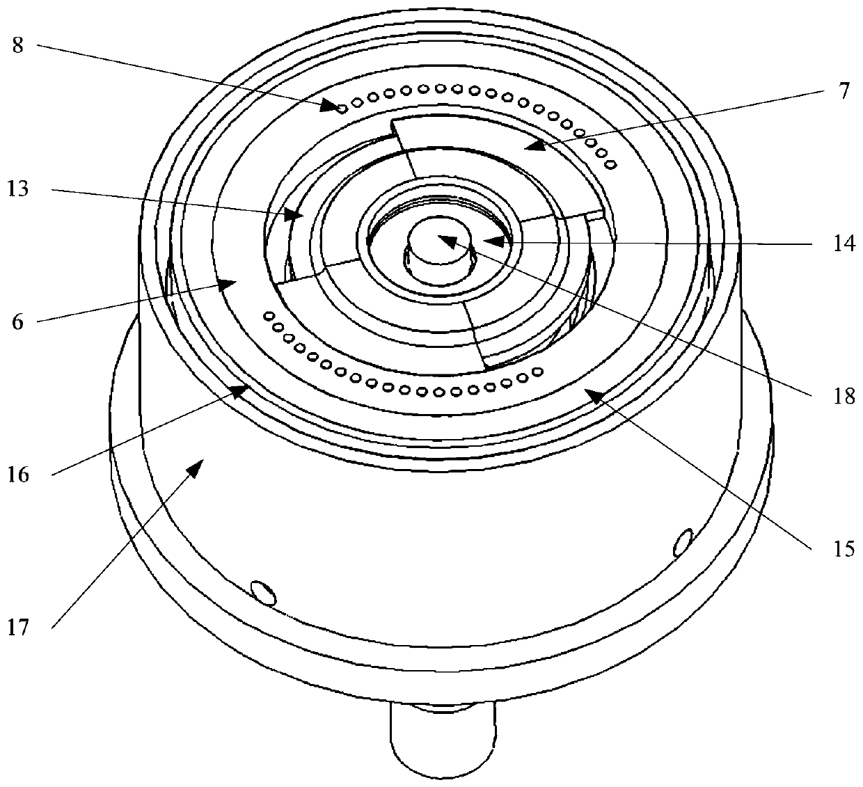
A variable damping vibration isolator based on ultrasonic motor adjustment comprises a base, a magneto-rheological damper and an adapter plate, and mainly utilizes the magneto-rheological damper to support and consume vibration energy. The magneto-rheological damper comprises an upper cavity, a lower cavity, a connecting ring, a permanent magnet, a throttling hole, a magnetic conductive ring, an ultrasonic motor and the like. Magneto-rheological fluid is stored in an upper cavity and a lower cavity formed by corrugated pipes, the middle section and the two ends of each cavity are used as inputand output ends of vibration, so the simulation piston movement of the damper without dynamic and static clearances is achieved, fluid is pushed to flow, fluid damping is provided, and leakage can beavoided during long-term on-orbit work. Moreover, the magneto-rheological damper adopts an ultrasonic motor to drive the permanent magnet to rotate, and the overlap ratio of the permanent magnet andthe throttling holes is adjusted, that is, the number of the throttling holes entering the magnetic field of the permanent magnet is adjusted, and the damping size of the damper is changed. After theultrasonic motor rotates in place, outage self-locking can be achieved. The ultrasonic motor is used for adjusting the number of the orifices in the magnetic field, and the damping is adjusted.

Description

technical field [0001] The invention relates to a variable damping vibration isolator based on ultrasonic motor adjustment, which belongs to the technical field of micro-vibration control. Background technique [0002] Inertial attitude actuators such as control moment gyroscopes have been widely used in high-precision spacecraft such as remote sensing satellites and space laboratories, and are key products for the spacecraft to achieve rapid attitude maneuvers and attitude stability. With the rapid development of aerospace technology, users have higher and higher requirements for satellite performance (such as camera resolution), and the payloads that realize these performances have higher and higher requirements for the attitude accuracy and stability of the spacecraft platform. However, during the high-speed rotation of the rotor of the inertial attitude actuator, it will produce a wide-band micro-vibration, which will become one of the main vibration sources of the space...

Claims


Application Information

Patent Timeline
IPC IPC(8): F16F9/53
CPCF16F9/535F16F2224/045F16F2222/06F16F9/3271F16F9/3292F16F2226/048F16F2230/0005F16F2230/0047
Inventor 罗睿智张激扬张强卿涛吴金涛田利梅樊亚洪
Owner BEIJING INST OF CONTROL ENG
Learn More