Energy-saving charger based on synchronous rectification technology

A synchronous rectification, charger technology, applied in electrical components, high-efficiency power electronic conversion, output power conversion devices, etc., can solve the problems of large heat generation, up and down fluctuations, and output fluctuations of the charger, and achieve reasonable structure and service life. The effect of effective control of long and calorific value

Pending Publication Date: 2020-04-10
中山市鹰飞电器有限公司
View PDF0 Cites 0 Cited by
  • Summary
  • Abstract
  • Description
  • Claims
  • Application Information

AI Technical Summary

Problems solved by technology

[0003] The purpose of the present invention is to provide an energy-saving charger based on synchronous rectification technology, which uses synchronous rectification to reduce part of the heat generation and solve the problem of large heat generation of the charger. In addition, because the input 220V power will fluctuate, the rectified 310V The power will fluctuate up and down, resulting in a certain fluctuation in the output. The PFC method is used to obtain a stable 385V DC, so as to achieve the purpose of stable output and improve the power factor at the same time.

Method used


Image

  • Energy-saving charger based on synchronous rectification technology
  • Energy-saving charger based on synchronous rectification technology
  • Energy-saving charger based on synchronous rectification technology

Examples


Embodiment Construction

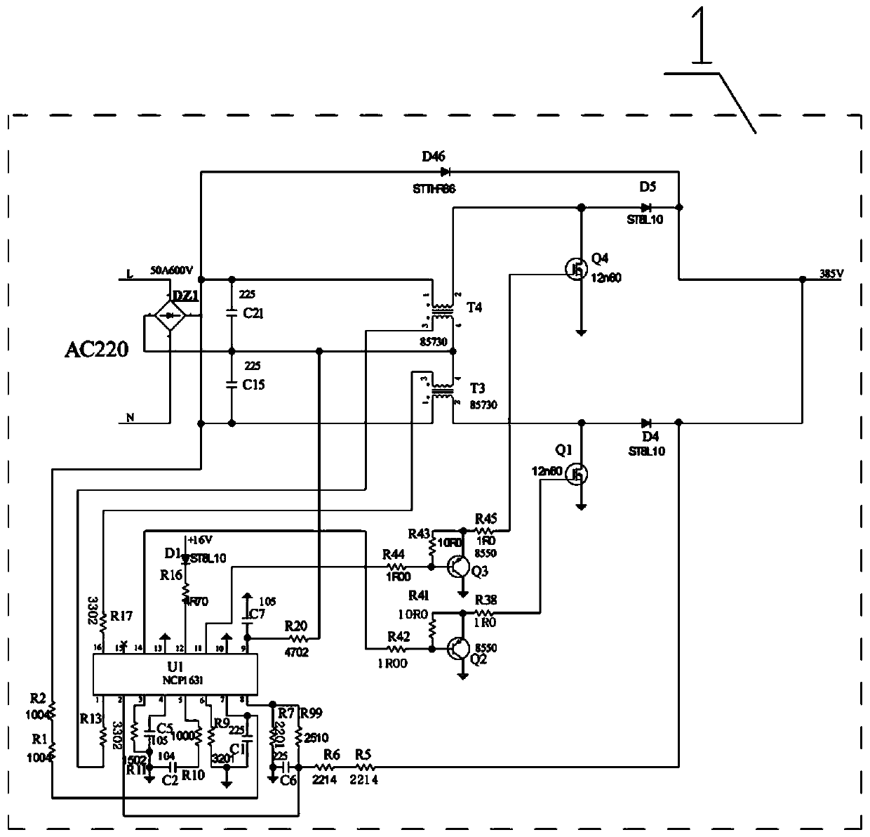
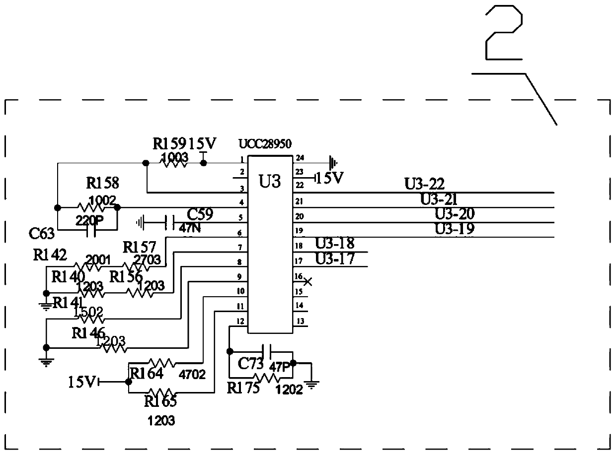
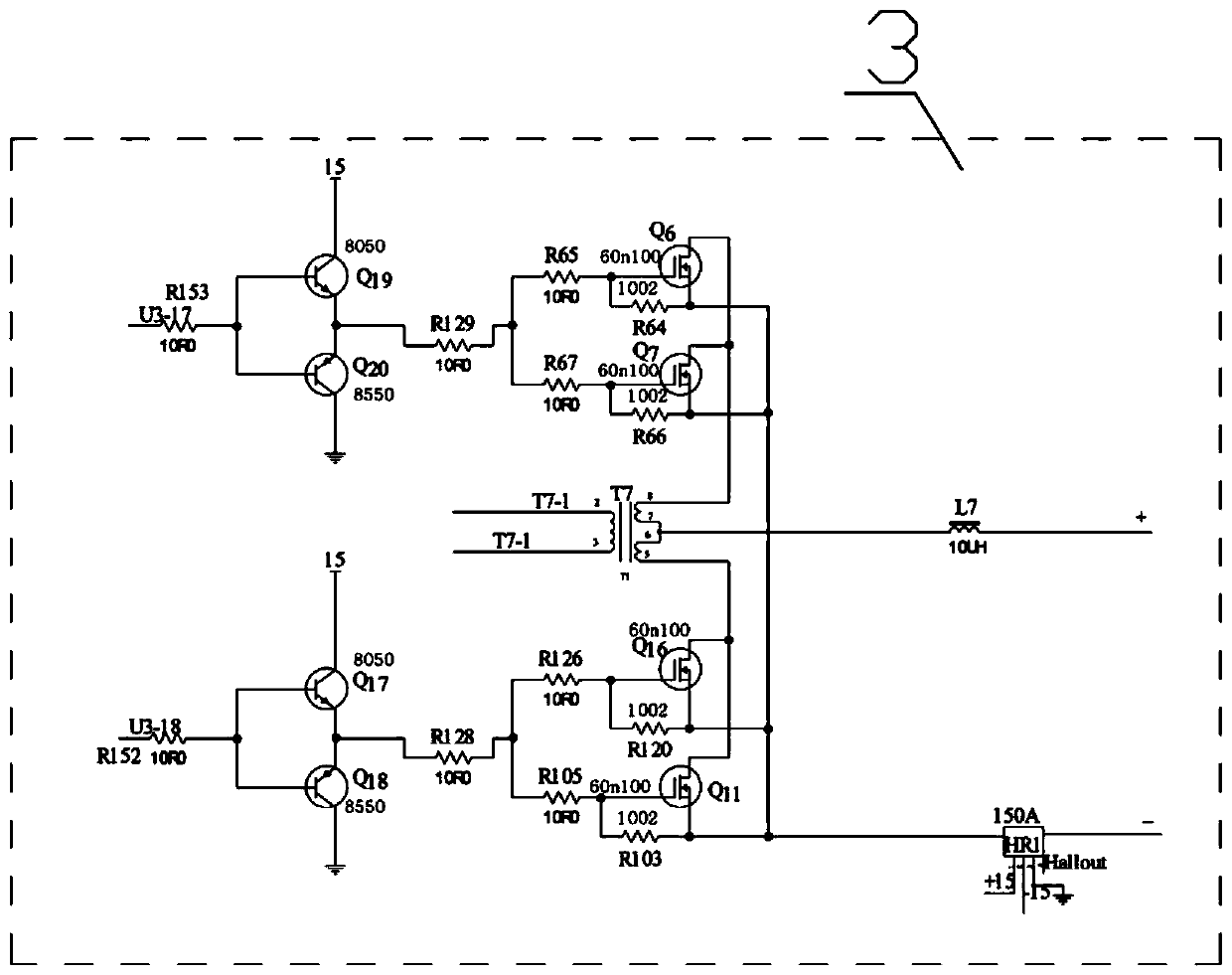
[0013] according to figure 1 , figure 2 , image 3 , Figure 4 Shown, among the present invention, chip U1 model is NCP1631, and U3 model is UCC28950, and triode Q3, Q2, Q17, Q18, Q19, Q20, model are 8550, and FET Q1, Q4 model are 12n60, and FET Q6, Q7 , Q16, Q11 model is 60n100, FET Q8, Q13, Q9, Q14 is 40n60, FET Q36, Q29, Q31, Q33 is IRF640, FET Q27, Q28, Q30, Q32 is IRF9530, On the basis of PFC circuit 1, drive circuit 2, synchronous rectification circuit 3, and inverter circuit 4, the characteristic is that the AC power of the PFC circuit 1 is rectified by the bridge rectifier DZ1 and then input to the primary stages of the alternating transformers T4 and T3, interleaved Parallel power factor corrector chip U1 outputs two interleaved working signals which are respectively amplified by transistors Q3 and Q2 and input to field effect transistors Q4 and Q1 to respectively control alternating transformers T4 and T3 to work alternately and output a stable 385V power supply ...


PUM


Abstract

The invention relates to an energy-saving charger based on a synchronous rectification technology, which is used for device charging. An alternating current power supply in a PFC circuit 1 is rectified and then input to a primary side of an alternating transformer, a chip U1 outputs two paths of interleaved working signals to control a field effect transistor to output a stable 385V power supply to the power supply input end of an inverter circuit 4, a driving circuit 2 outputs four paths of inversion signals to the inversion signal input end of the inverter circuit 4, so that the field effecttransistor controls the two driving transformers to work primarily, the two driving transformers work to drive four MOS transistors of a full bridge, and the main transformer secondary outputs the inversion power supply to the power supply input end of a synchronous rectification circuit 3; the driving circuit 2 outputs two paths of synchronous drive signals to the synchronous signal input end ofthe synchronous rectification circuit 3, and rectifies and outputs two groups of secondary sides of the transformer through the field effect transistor. The energy-saving charger has the advantages of the reasonable and stable structure and the long service life, can continuously work for a long time, and can effectively control the heat productivity of the whole machine.

Description

technical field [0001] The invention relates to an energy-saving charger based on synchronous rectification technology. Specifically, a drive circuit controls a synchronous rectification circuit and an inverter circuit to invert a stable current provided by a PFC circuit and then synchronously rectifies and outputs it. Background technique [0002] Generally, the charger adopts the half-bridge and full-bridge structure, and the output rectification generally adopts full-wave rectification, because it is diode rectification, the loss is very large, which makes the temperature of the whole machine increase, and the output voltage will have ripples according to the fluctuation of the input 220V power. , affect the stability of the output, without PFC circuit, the power factor is low, because it is diode rectification, which makes the temperature of the whole machine rise, affects the working temperature of the whole machine, cannot work for a long time, and reduces the charging ...

Claims


Application Information

Patent Timeline
Patent Type & Authority Applications(China)
IPC IPC(8): H02M1/42H02M1/088H02M7/219H02M7/5387
CPCH02M1/088H02M1/4208H02M7/219H02M7/5387Y02B70/10
Inventor 杨毅博秦国花张云锟
Owner 中山市鹰飞电器有限公司
Why Eureka
Try Eureka