Device for controlling electron flow and method for manufacturing said device

A technology for controlling electronics and controlling electrodes, which is applied in the manufacture of electrode components, support/installation/spacing/insulation of electrode components, electrostatic control tubes, etc. It can solve problems such as device time degradation, incomplete vacuum, and emitter exposure, and achieve Effects of enhanced control, improved efficiency, and reduced device cost

Pending Publication Date: 2020-04-10
EVINCE TECH LTD
View PDF4 Cites 0 Cited by
  • Summary
  • Abstract
  • Description
  • Claims
  • Application Information

AI Technical Summary

Problems solved by technology

The problem with any field emission source made in this way is that the emitter is exposed to an imperfect vacuum
Therefore, it is inevitable that there will be a small amount of residual gas that will be partially ionized by the emitted electrons, and these ions, which are tens of thousands of times heavier than electrons, will be attracted back to the emitter, causing impact and causing damage
Therefore, all devices manufactured in this way will degrade over time

Method used


Image

  • Device for controlling electron flow and method for manufacturing said device
  • Device for controlling electron flow and method for manufacturing said device
  • Device for controlling electron flow and method for manufacturing said device

Examples


Embodiment Construction

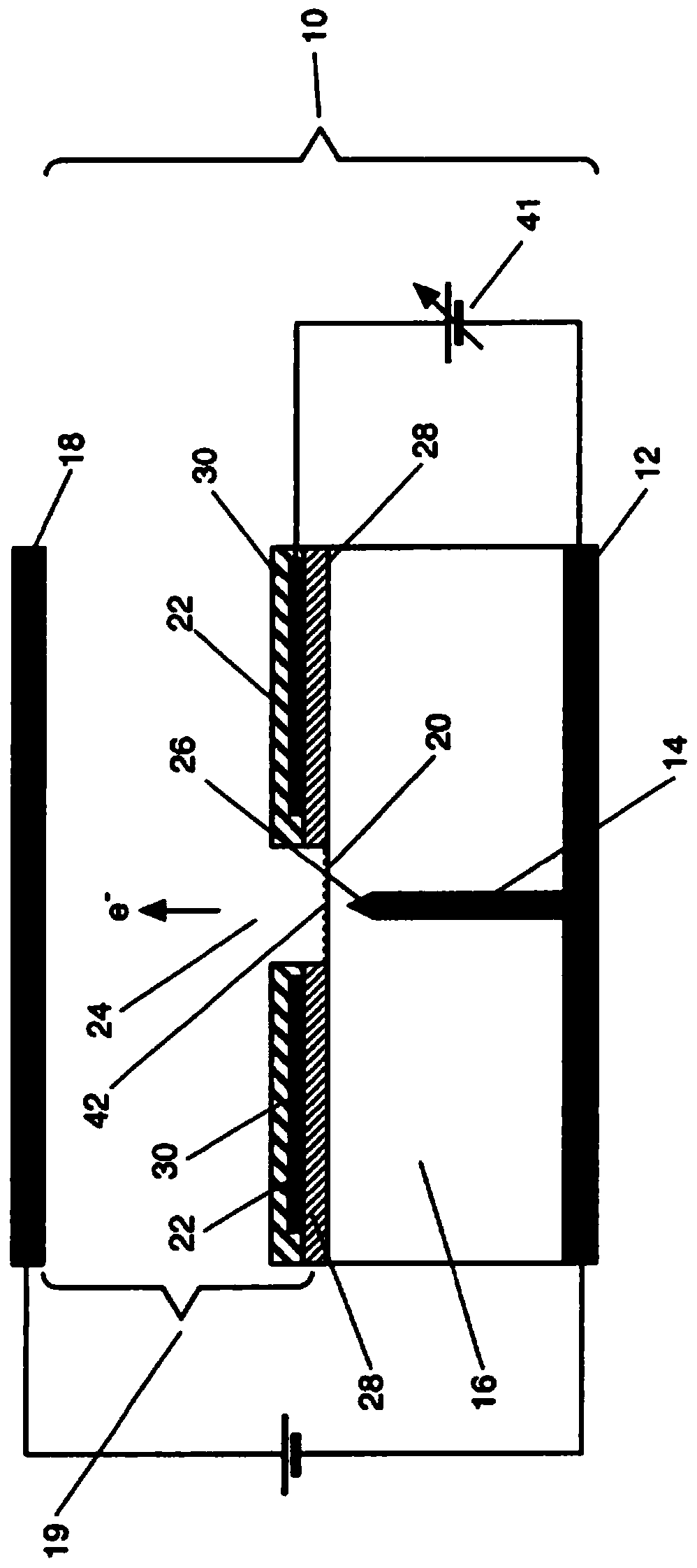
[0114] refer to figure 1 , shows a device 10 for controlling the flow of electrons comprising a cathode 12; an electron source in the form of an elongated electrical conductor 14 embedded in a diamond substrate 16 and in contact and electrical communication with the cathode 12; an anode 18 consisting of A space or void 19 is spaced from the surface 20 of the substrate 16; and a control electrode 22 is disposed on the surface 20 of the substrate. Diamond substrate 16 may comprise intrinsic diamond, nitrogen-doped diamond, or a combination of both. The control electrode shown includes an opening 24 peripherally surrounding an end 26 of the conductor 14 . The exposed portion of surface 20 adjacent end 26 of conductor 14 is treated to exhibit a negative electron affinity. In all figures, the negative electron affinity (NEA) treated surface 42 is indicated by dashed lines. The control electrode 22 is isolated from the substrate 16 using a layer of insulating material 28 and furt...


PUM

PropertyMeasurementUnit
melting pointaaaaaaaaaa

Abstract

A device (10) for controlling electron flow is provided. The device comprises a cathode (12), an elongate electrical conductor (14) embedded in a diamond substrate (16), an anode (18), and a control electrode (22) provided on the substrate surface (20) for modifying the electric field in the region of the end (26) of the conductor (14). A method of manufacturing the device (10) is also provided.

Description

technical field [0001] The present invention relates to devices for controlling the flow of electrons and in particular, but not exclusively, to electric field modulating devices comprising elongated conductors embedded in diamond. The invention also relates to a method of manufacturing a device for controlling the flow of electrons. Background technique [0002] It is well known that heated thermionic cathodes can be used to generate free electrons. Devices incorporating these cathodes have a number of disadvantages, including: the need to heat the cathode to approximately 1,000°C to 1,200°C; mechanical fragility of the cathode structure; additives (such as barium) to enhance the emission process poisoning; and a limited emission current density, typically 2 to 3 amps per square centimeter, which, if increased, exponentially degrades the lifetime of the cathode. [0003] Vacuum field emission electron sources (also known as cold cathodes) have been the subject of research...

Claims


Application Information

Patent Timeline
Patent Type & Authority Applications(China)
IPC IPC(8): H01J1/304H01J3/02H01J21/10
CPCH01J1/3044H01J3/022H01J3/027H01J21/105H01J2201/30415H01J2201/30426H01J9/18H01J19/30H01J19/38H01J19/44H01J19/48
Inventor 格丽斯·安德鲁·泰勒戴维·安德鲁·詹姆斯·莫兰约翰·彼得·卡尔保罗·法勒马克·基兰·梅西
Owner EVINCE TECH LTD
Why Eureka
Try Eureka