Planar horn antenna with filtering function and filter antenna

A horn antenna, planar technology, applied in the direction of waveguide horn, antenna coupling, antenna grounding device, etc., can solve the problems of horn change, affect antenna radiation performance, bulkiness, etc., and achieve the effect of expanding bandwidth

Active Publication Date: 2020-04-14
XIDIAN UNIV
View PDF6 Cites 3 Cited by
  • Summary
  • Abstract
  • Description
  • Claims
  • Application Information

AI Technical Summary

Problems solved by technology

[0003] To sum up, the problem existing in the prior art is that most of the existing devices related to filter horn antennas in the prior art are obtained by adding a filter structure to the metal pyramid horn, which is more complicated than the structure of the substrate-type filter horn antenna. Relatively complex, relatively large and cumbersome, relatively cumbersome design, does not meet the trend of terminal miniaturization
[0005] Significance of solving the above-mentioned technical problems: In order to realize the miniaturization of the equipment size, the present invention designs and uses the substrate integrated waveguide technology, because the profile of the dielectric substrate is too low, the matching of the horn antenna is poor, and adding a filter structure inside the horn antenna will make the The internal field distribution of the horn changes, which affects the radiation performance of the antenna

Method used


Image

  • Planar horn antenna with filtering function and filter antenna
  • Planar horn antenna with filtering function and filter antenna
  • Planar horn antenna with filtering function and filter antenna

Examples


Embodiment Construction

[0034] In order to make the object, technical solution and advantages of the present invention more clear, the present invention will be further described in detail below in conjunction with the examples. It should be understood that the specific embodiments described here are only used to explain the present invention, not to limit the present invention.

[0035] Aiming at the problems existing in the prior art, the present invention provides a planar horn antenna and a filter antenna with a filtering function. The present invention will be described in detail below with reference to the accompanying drawings.

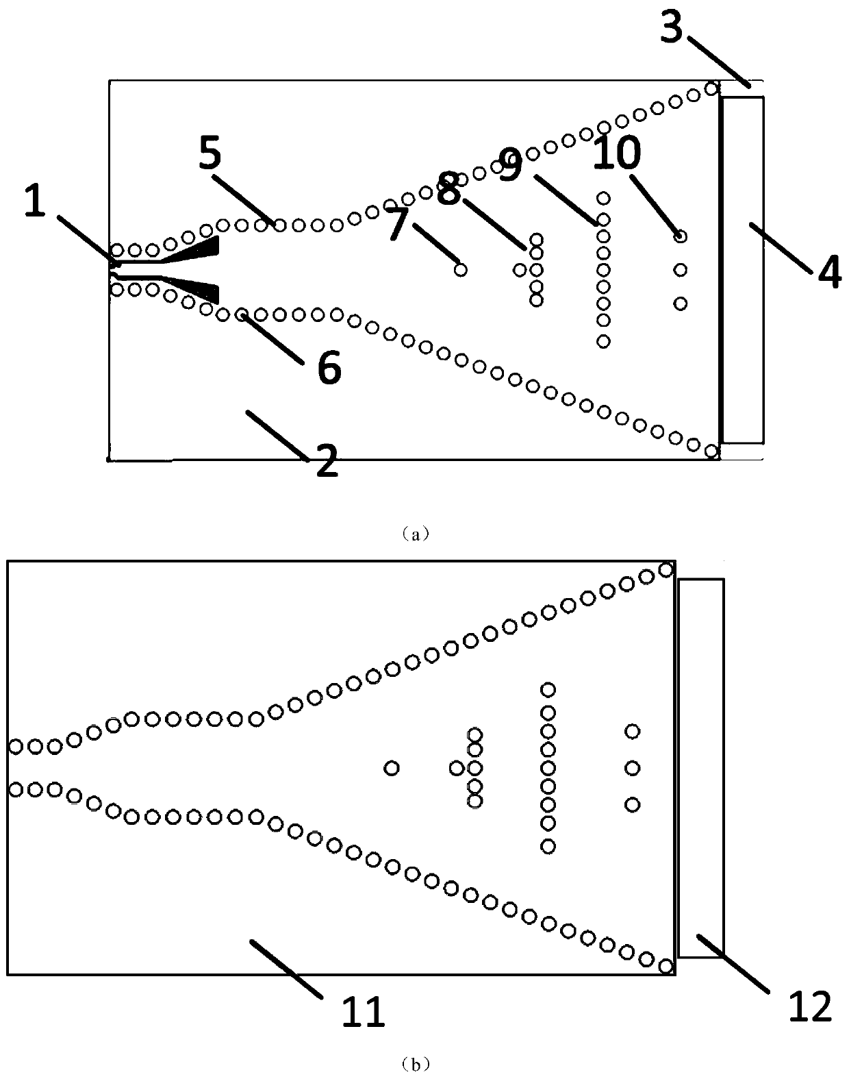
[0036] Such as figure 1 As shown, the planar horn antenna with filtering function provided by the embodiment of the present invention includes: a feed structure, a dielectric substrate 3, and a filter antenna; the metal ground plane 11 and the right end located on the lower surface of the dielectric substrate 3 are used to improve substrate integration The radiation ...


PUM


Abstract

The invention belongs to the technical field of antennas, and discloses a planar horn antenna and filter antenna with a filtering function, which comprises a filtering structure, a radiation structure, a feed structure, a dielectric substrate and a metal floor. The grounding coplanar waveguide is used for feeding a horn antenna, metal floors are arranged on the upper surface and the lower surfaceof the dielectric substrate, the filtering structure is a metallized through hole array embedded in a horn, and finally signals are radiated through the caliber of the horn antenna on the right side.According to the antenna, the horn antenna is printed on a PCB by adopting a planar single-layer structure, the filtering structure is additionally arranged in the horn antenna, the filtering functionis achieved under the condition that the equipment size is not increased, and the antenna is simple and compact in structure and easy to integrate; the antenna works at 16.3 GHz to 17.1 GHz, and hasgood in-band selection and out-of-band rejection characteristics in a frequency band; the defect that a traditional filter antenna is large in design size is overcome, the filter and the antenna are integrally designed, the size is further reduced, the manufacturing cost is low, and the filtering structure is simple in design.

Description

technical field [0001] The invention belongs to the technical field of antennas, and in particular relates to a planar horn antenna and a filter antenna with a filtering function. Background technique [0002] At present, the closest existing technology: in wireless communication systems, antennas and filters are essential, but in traditional wireless communication system design, antennas and filters are designed separately, and then directly cascaded, the antenna and filter Impedance connection ports must match the characteristic impedance of 50Ω in most cases. And the addition of the impedance matching network will increase the device size and insertion loss of the radio frequency front end. In order to solve the above problem, a new design concept is proposed, that is, filter antenna. This design method is to integrate the filter and antenna into one device, so that it has the functions of filter filtering clutter and antenna radiation signal at the same time. In the d...

Claims


Application Information

Patent Timeline
Patent Type & Authority Applications(China)
IPC IPC(8): H01Q13/02H01Q1/38H01Q1/48H01Q1/50H01Q1/52
CPCH01Q13/02H01Q1/38H01Q1/48H01Q1/50H01Q1/52
Inventor 邓敬亚白陶龙孙冬全雍婷郭立新
Owner XIDIAN UNIV
Why Eureka
Try Eureka