W-flame boiler adopting slit type combustor

A slot type, burner technology, applied in burners, burners that use multiple fuels, and burners that burn powder fuels, etc., can solve problems such as fire extinguishing and combustion instability, improve ignition characteristics, and improve low-load stable combustion. effect of ability

Active Publication Date: 2020-04-17
HARBIN INST OF TECH
View PDF10 Cites 1 Cited by
  • Summary
  • Abstract
  • Description
  • Claims
  • Application Information

AI Technical Summary

Problems solved by technology

[0007] The purpose of the present invention is to solve the problem of unstable combustion or even fire extinguishing when the boiler load is lower than 50% when the traditional W flame b

Method used


Image

  • W-flame boiler adopting slit type combustor
  • W-flame boiler adopting slit type combustor
  • W-flame boiler adopting slit type combustor

Examples


specific Embodiment approach 1

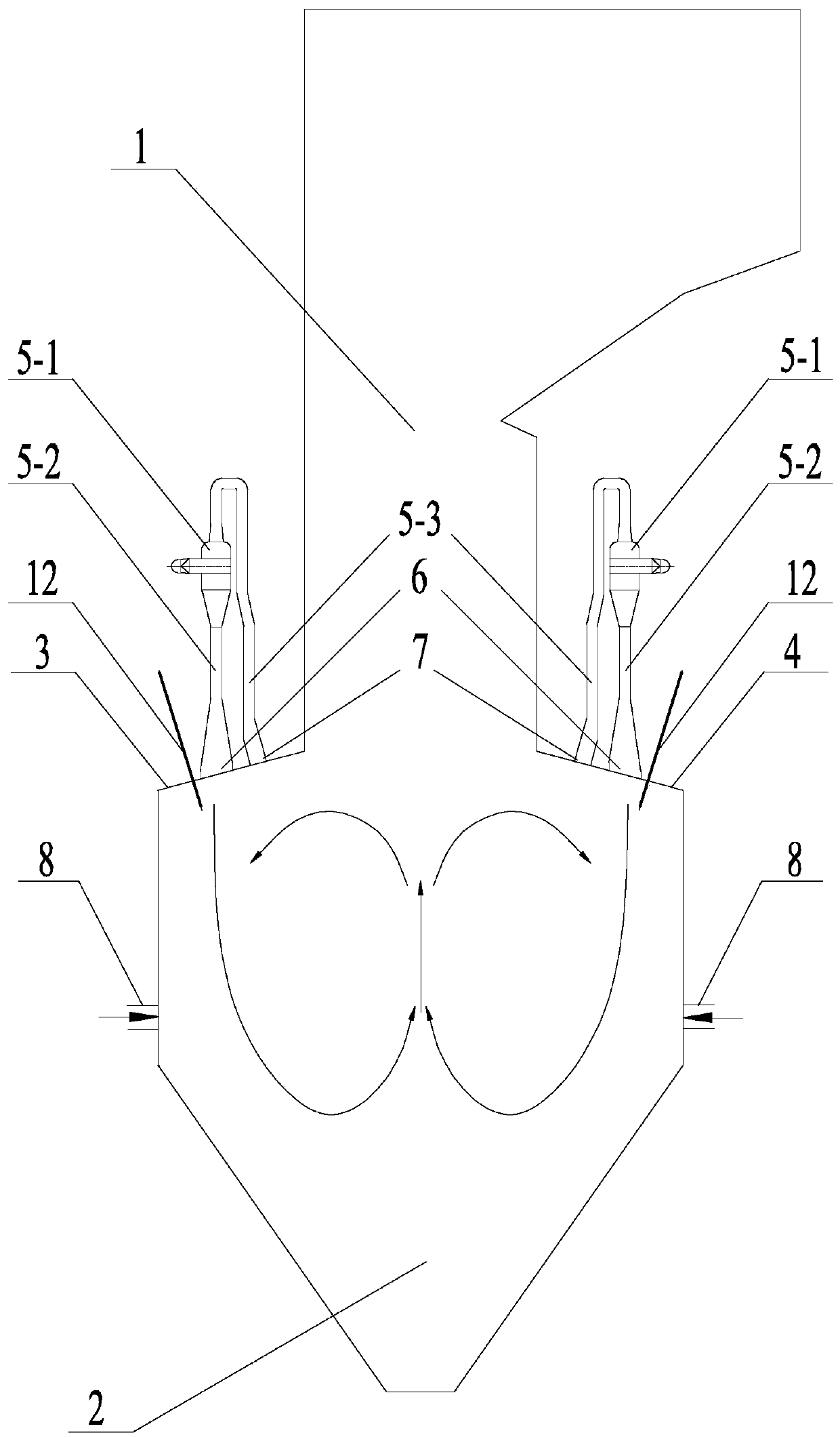
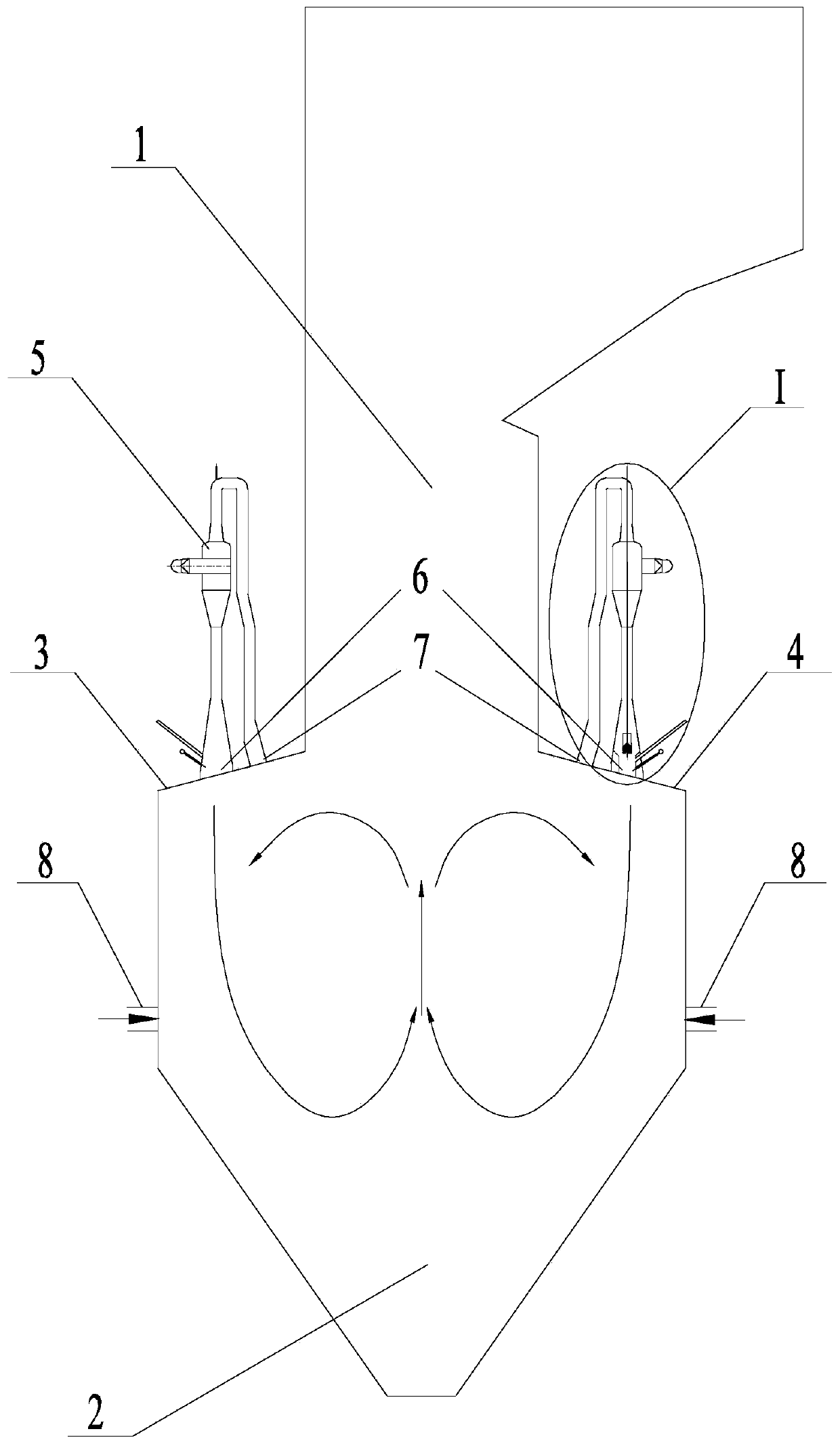
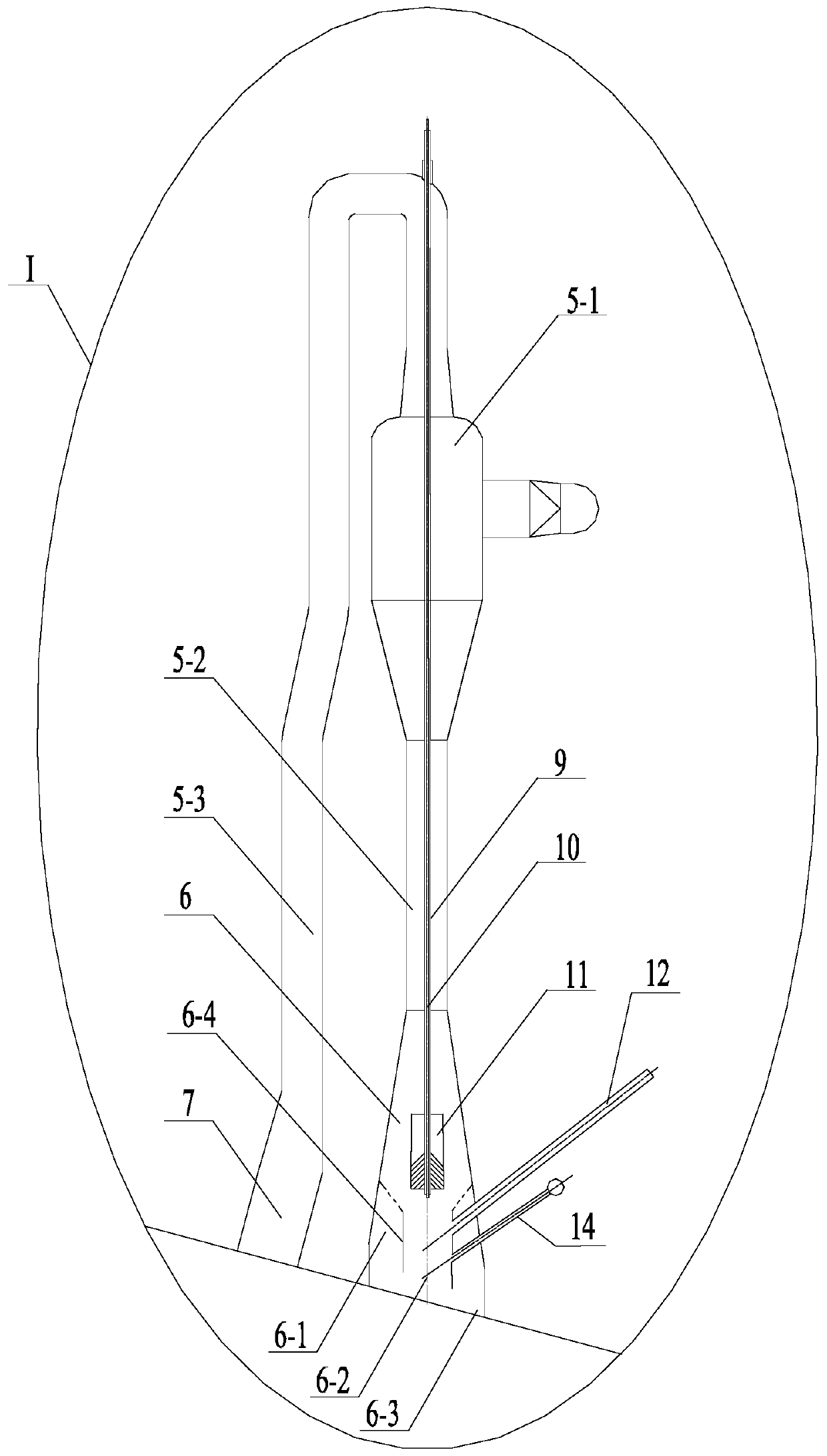
[0024] Specific implementation mode one: combine Figure 2-Figure 4 Describe this embodiment, the W-flame boiler using slot burners described in this embodiment includes an upper furnace 1, a lower furnace 2, a front furnace arch 3, a rear furnace arch 4, a front wall, a rear wall, and a plurality of direct current gaps Type burner 5 and multiple graded air nozzles 8; DC slot burner 5 includes hollow swirl adjustment rod 9, micro-oil ignition gun 10 and pulverized coal guide body 11, upper furnace 1, front furnace arch 3, front wall, The lower furnace 2, the rear wall and the rear furnace arch 4 constitute the furnace body. The micro-oil ignition gun 10 is installed in the hollow swirl adjustment rod 9, and the bottom end of the hollow swirl adjustment rod 9 is fixedly connected with the pulverized coal guide body 11. The adjustment rod 9, the micro-oil ignition gun 10 and the pulverized coal guide body 11 are installed in the shell of the DC slot burner 5, the front wall and ...

specific Embodiment approach 2

[0025] Specific implementation mode two: combination Figure 2-Figure 4 Describe this embodiment, the W-flame boiler using slot burners described in this embodiment, a plurality of direct current slot burners 5 on the water wall of the front furnace arch 3 are arranged in a straight line, and many on the water wall of the rear furnace arch 4 Two direct-flow slot burners 5 are arranged in a straight line, and other methods are the same as the specific embodiment one.

specific Embodiment approach 3

[0026] Specific implementation mode three: combination Figure 2-Figure 4 Describe this embodiment, the W-flame boiler using the gap burner described in this embodiment, the direct current gap burner 5 also includes a cyclone 5-1, a concentrated pulverized coal pipeline 5-2, an exhaust gas pipeline 5-3, a concentrated Pulverized coal air flow nozzle 6 and light coal powder air flow nozzle 7, exhaust gas pipeline 5-3, cyclone 5-1 and thick coal powder pipeline 5-2 are connected in sequence, and exhaust gas pipeline 5-3 is connected with light coal powder air flow nozzle 7 , the thick coal powder pipeline 5-2 is connected with the thick coal powder airflow nozzle 6, and the thick coal powder airflow nozzle 6 and the light coal powder airflow nozzle 7 of each direct current slot type burner 5 on the front furnace arch 3 water wall are all connected with the fore furnace The arch 3 is connected to the water wall, and the dense coal powder airflow nozzle 6 and the light coal powder...


PUM


Abstract

The invention discloses a W-flame boiler adopting a slit type combustor, and relates to a W-flame boiler adopting a flexible peak regulation technology. The W-flame boiler adopting the slit type combustor aims to solve the problems that when the load of the conventional W-flame boiler is lower than 50 percent by adopting an oil gun ignition mode, the combustion is unstable and even the fire is extinguished; and the flexible peak regulation capacity of the boiler needs to reach 20% of full load, but a boiler meeting the condition does not exist in the prior art. The W-flame boiler comprises anupper hearth, a lower hearth, a front boiler arch, a rear boiler arch, a front wall, a rear wall, a plurality of straight flow gap type combustors and a plurality of grading air nozzles; and each straight flow gap type combustor comprises a hollow rotational flow adjusting pull rod, a tiny-oil burning torch and a pulverized coal flow guiding body, wherein the tiny-oil burning torch is installed inthe hollow rotational flow adjusting pull rod, the bottom end of the hollow rotational flow adjusting pull rod is fixedly connected with the pulverized coal flow guiding body, and the hollow rotational flow adjusting pull rod, the tiny-oil burning torch and the pulverized coal flow guiding body are installed in the straight flow gap type combustor shell. The invention belongs to the field of boilers.

Description

technical field [0001] The invention relates to a W-flame boiler adopting flexible peak-shaving technology, in particular to a W-flame boiler adopting a gap burner. Background technique [0002] In recent years, with the intervention of large-scale renewable energy, China's power system has undergone tremendous changes. Renewable energy generation capacity is taking an increasing share in the grid. However, due to the limitations of the power generation method itself, the output instability of renewable energy power generation poses a huge challenge to the regulation capability of the power system; in addition, a large number of uncertain factors on the power generation side and the demand side also affect the security and stability of the power system run. Statistics show that in 2015, China's annual net thermal power installed capacity was 72.02 million kilowatts (including 51.86 million kilowatts of coal-fired power), which was the largest annual production since 2009. ...

Claims


Application Information

Patent Timeline
IPC IPC(8): F23C5/08F23D1/00F23K3/02F23L7/00
CPCF23C5/08F23D1/00F23K3/02F23L7/007Y02E20/34
Inventor 李争起杜贺郑智巍刘文杰曾令艳陈智超
Owner HARBIN INST OF TECH
Why Eureka
Try Eureka