Permanent magnet synchronous motor prediction current control method and device

A permanent magnet synchronous motor and current prediction technology, which is applied in motor control, motor generator control, electromechanical transmission control, etc., can solve the problems of complex calculation of non-zero vector action time, error of solution method, error of control method, etc.

Active Publication Date: 2020-04-17
湖南天正友选企业策划有限公司
View PDF6 Cites 12 Cited by
  • Summary
  • Abstract
  • Description
  • Claims
  • Application Information

AI Technical Summary

Problems solved by technology

The three-vector predictive current control can effectively reduce the torque ripple and the total harmonic distortion rate of the stator current, but in the three-vector predictive control overmodulation optimization method, the vector action time expression contains trigonometric functions, and the calculation is more complicated
However, in the CN201610321625.7 patent, when the vector action time is greater than the sampling period, the processing method adopted is to linearly reduce the action time to within the sampling period, there is still a certain error, and the calculation of the non-zero vector action time is relatively complicated; After the vector action time, it is necessary to determine whether it is overmodulated, and there is a problem of large amount of calculation.
[0007] In addition, in the patent "CN201810787417.5-A two-vector predictive control system and method for permanent magnet synchronous motor based on geometric method", its paragraphs 65-70 and figure 2 There are a large number of trigonometric functions in the calculation of determining the alternative voltage vector and dual voltage vector selection, which increases the complexity and amount of calculation of the action time based on the duty cycle. There are errors in the control method for over-modulation, and there is no For the subdivision of the III+ area, after calculating the action time, it must be judged that t>T s , t At this time, the action time is greater than or equal to T s , if t>T s Then let t=T s , if t<0 then let t=0)
In addition, in the CN201810787417.5 patent, the action time is calculated by dividing the projected length d by the side length. image 3 (b) d is V op The projection length on the BC side, this solution method has a large error, for example, when V op When it coincides with AO and p is on BC, d=0, u 1 and u 2 A certain action time is 0, the error is BC / 2, and according to the error calculation method of the prior art, the error is equal to 0, so there is a large error in the solution method
[0008] To sum up, it can be seen that in the existing prior art, the two-vector predictive current control for permanent magnet synchronous motors driven by two-level inverters still adopts the traditional processing method; The calculation of the modulation optimization method is still complicated. For the predictive control of the permanent magnet synchronous motor, there is still a lack of a method that can simultaneously reduce the torque ripple and the total harmonic distortion of the stator current, improve the steady-state performance, improve the existing over-modulation optimization method, reduce The use of trigonometric functions to reduce the PMSM predictive current control method or device of the calculation amount of the motor control algorithm

Method used


Image

  • Permanent magnet synchronous motor prediction current control method and device
  • Permanent magnet synchronous motor prediction current control method and device
  • Permanent magnet synchronous motor prediction current control method and device

Examples


Embodiment Construction

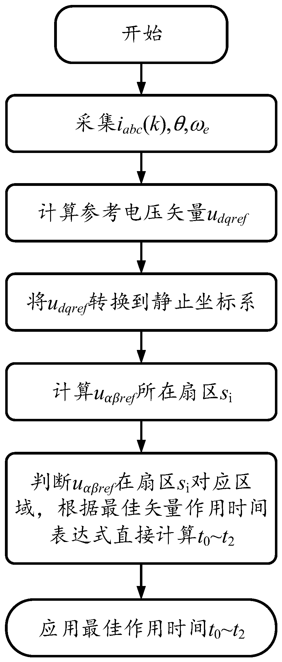
[0077] The specific implementation manners of the present invention will be further described in detail below in conjunction with the accompanying drawings and embodiments. The following examples are used to illustrate the present invention, but are not intended to limit the scope of the present invention.

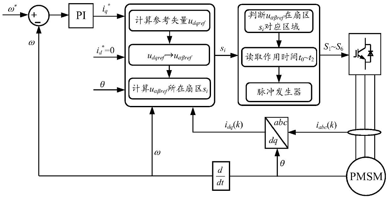
[0078] figure 1It is a system structure diagram of the present invention, mainly including a DC power supply, a three-phase two-level voltage source inverter, a controller, and a permanent magnet synchronous motor. Among them, the permanent magnet synchronous motor is used as the controlled unit, and the three-phase voltage source inverter is used as the power module to drive the controlled unit. The controller collects the mechanical and electrical quantities of the motor system from the controlled unit, and then uses the control of the present invention The method is used to select the optimal control vector and input it to the inverter through the modulation unit to r...


PUM


Abstract

The invention discloses a permanent magnet synchronous motor prediction current control method and device. According to the predictive current control method, the direct-current bus voltage, the three-phase current, the rotor rotation electrical angular velocity and the rotor electrical angle of the permanent magnet synchronous motor at the current moment are sampled; the reference voltage vectorof the static coordinate system is calculated and obtained, the multi-region division method for basic voltage vector sectors is proposed, an optimal vector is selected under the condition of considering overmodulation, and the accurate simplified expression of the optimal action time of each basic voltage vector is finally given. Therefore, the method provided by the invention can improve the existing overmodulation optimization method and can reduce the use of trigonometric functions, greatly reduces the calculated amount, further reduces the quadrature-direct axis current ripples of the permanent magnet synchronous motor, reduces the torque ripple and the total harmonic distortion rate of the stator current, and improves the steady-state performance of the system.

Description

technical field [0001] The invention relates to the field of motor control methods, and more specifically, to a method and device for predicting current control of a permanent magnet synchronous motor. Background technique [0002] Permanent magnet synchronous motors have been widely used in electric vehicles and other power transmission fields due to their high power density, high efficiency, and good reliability. The quality of the motor control strategy directly determines the performance of the drive system. With the urgent need for the industrialization of electric drives, the requirements for high efficiency, high density and high reliability of electric drive systems are becoming increasingly stringent. Currently, the most widely used AC motor control methods are Field Oriented Vector Control (FOC) and Direct Torque Control (DTC). Although the traditional FOC has the advantages of good steady-state performance and small torque ripple, because its current inner loop ...

Claims


Application Information

Patent Timeline
Patent Type & Authority Applications(China)
IPC IPC(8): H02P21/22H02P21/14
CPCH02P21/14H02P2205/01H02P2207/05H02P21/22
Inventor 刘平刘超黄守道苗轶如童林林陈常乐
Owner 湖南天正友选企业策划有限公司
Why Eureka
Try Eureka