Laser welding method and system for end faces of copper and copper alloy plates with different thicknesses

A laser welding and alloy plate technology, applied in laser welding equipment, welding equipment, metal processing equipment, etc., can solve the problems of reduced welding performance, lack of copper and its alloy end face welding methods, unsatisfactory, etc., and achieve a smooth transition effect

Active Publication Date: 2020-04-21
CHINA-UKRAINE INST OF WELDING GUANGDONG ACAD OF SCI
View PDF10 Cites 9 Cited by
  • Summary
  • Abstract
  • Description
  • Claims
  • Application Information

AI Technical Summary

Problems solved by technology

However, the above advantages will be greatly reduced when laser welding metals with high reflectivity and good thermal conductivity, such as copper and its alloys. The common welding copper alloy methods except TIG welding, MIG welding and brazing greatly limit the welding efficiency of copper alloys. and reduced soldering performance
The existing green lasers use the laser in the green band to increase the absorption rate of copper and its alloys to improve the welding quality of laser welding copper and alloys. However, due to equipment capacity problems, currently only 1-2mm copper sheets can be welded by stitch welding. It is far from being able to meet and adapt to the welding needs of copper and its alloys in the rapid development of the electronics and new energy industries. In addition to the increase in the thickness of welding copper and its alloys, the welding of different thicknesses and the connection of end faces also increase the complexity of welding. At the same time, the end face Joint electrical conductivity and mechanical properties require higher welding quality
[0003] Therefore, there is a lack of effective copper and its alloy end face welding methods in the prior art

Method used


Image

  • Laser welding method and system for end faces of copper and copper alloy plates with different thicknesses
  • Laser welding method and system for end faces of copper and copper alloy plates with different thicknesses
  • Laser welding method and system for end faces of copper and copper alloy plates with different thicknesses

Examples


Embodiment 1

[0068] The laser welding method for the end faces of copper and its alloy plates with different thicknesses provided in this embodiment is specifically:

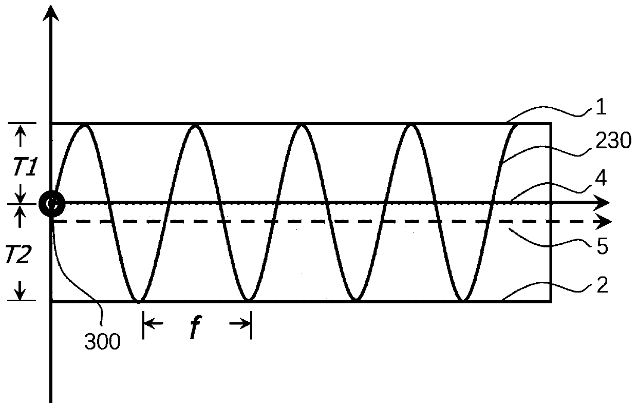
[0069] Red copper with a thickness of 3 mm and a thickness of 5 mm is used as the welding test piece, the welding position is the end face position, the welding depth is 4 mm, and the length of the structural part is 100 mm. According to the requirements of the welding depth, the laser power is 6000W, the outer ring laser beam 302 is set to 1200W, and the center laser beam 301 is set to 100% to 6000W; according to the plate thickness, the laser swing amplitude is set to 4mm, and the swing frequency is 150Hz. Before welding, according to the thickness of the first plate 1 and the second plate 2, the movement route of the laser head is set, parallel to the welding direction 4, and the vertical direction of the weld 3 is negatively deviated by 1mm, and the laser beam movement trajectory 230 is according to Y=4sin(300πt +0.25) m...

Embodiment 2

[0073] Red copper with a thickness of 4mm and 8mm is used as the welding test piece, the welding position is the end face position, the welding depth is 5mm, and the length of the structural part is 100mm. Select laser power 6500W according to welding depth requirements, outer ring laser beam 302 is set to 1200W, center laser beam 301 is set to 100% to 6000W; according to plate thickness, laser swing amplitude is set to 6mm, and swing frequency is 200Hz. Before welding, set according to copper plate thickness The laser head movement route is parallel to the welding direction 4, and the vertical direction of the weld 3 is negatively deviated by 2mm. The laser beam movement trajectory 230 moves according to Y=6sin(400πt+0.34). During the welding process, the laser beam power follows the laser beam movement trajectory. The multi-line center laser power change curve 210 and the outer ring laser power change curve 220 are adjusted to ensure that the center laser beam 301 matches the...

Embodiment 3

[0075] This embodiment is basically the same as Embodiment 1, except that brass different from Embodiment 1 is used as the welding test piece. The laser power is 5000W, and the laser swing frequency is 200Hz.

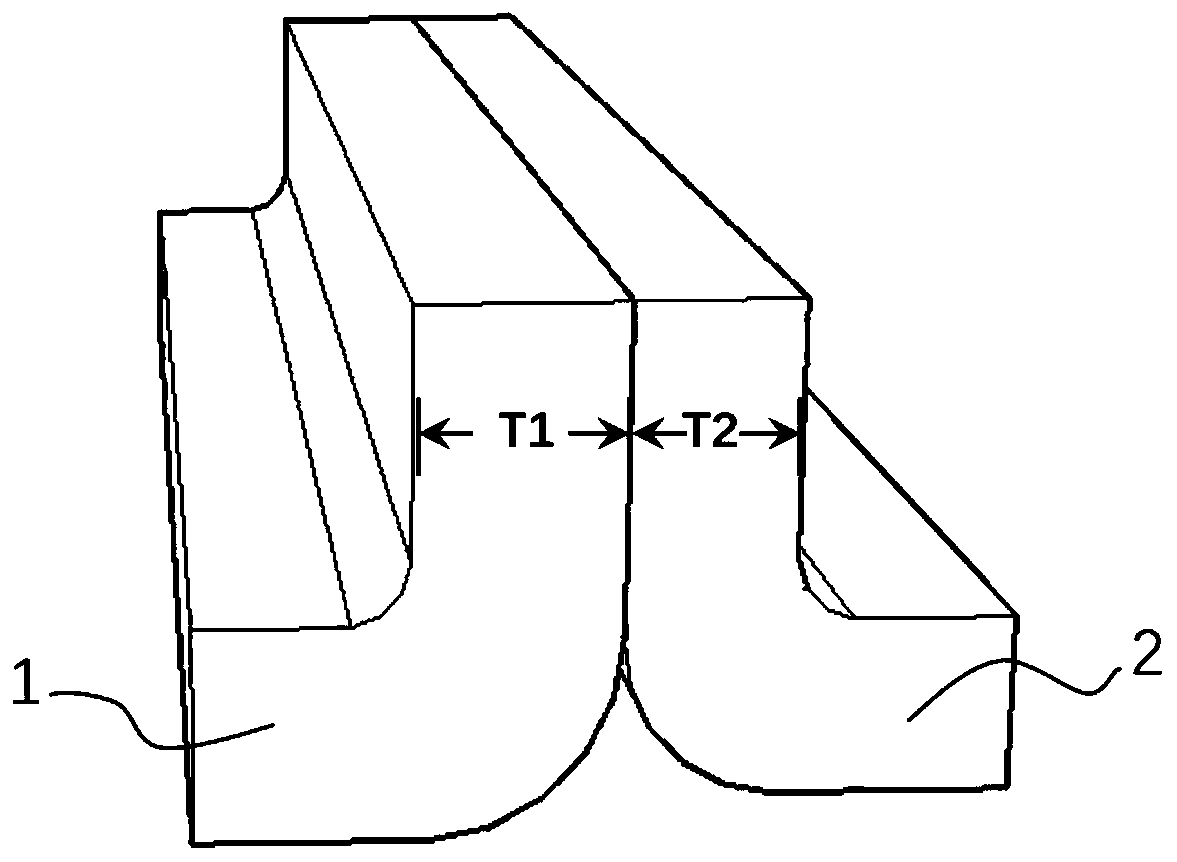
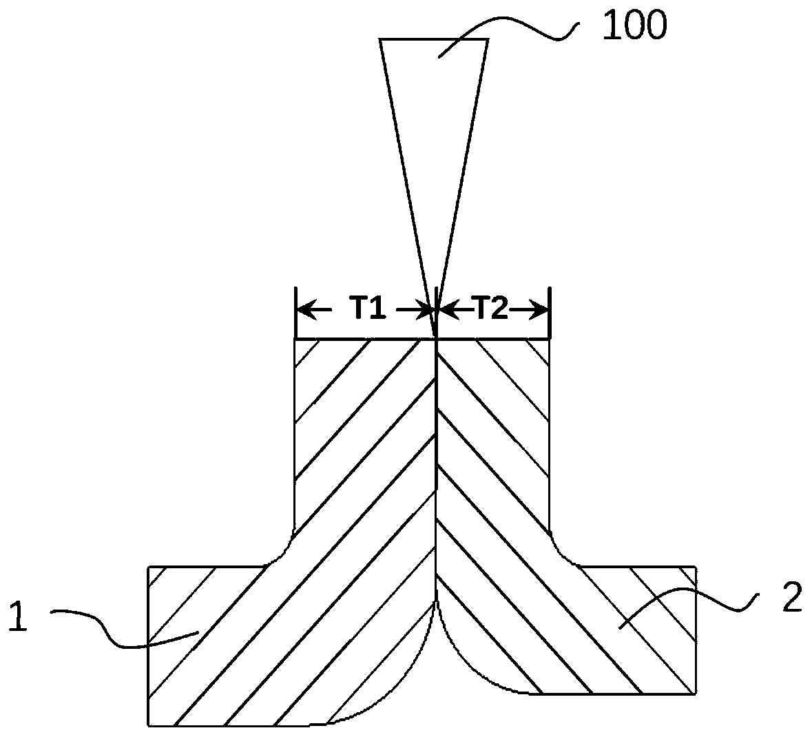
[0076]In summary, the laser welding method for the end faces of copper with different thicknesses and its alloy plates provided by the embodiment of the present invention aims at the welding problems that occur in the laser welding of the end faces of copper with different thicknesses and its alloy plates. Swing welding, and set the swing amplitude, swing frequency and laser beam power of the laser beam 300 respectively according to the thickness of the first plate 1 and the second plate 2 to be welded, and form the outer ring laser beam 302 through laser shaping of the laser beam 300 and the center laser beam 301, wherein the outer ring laser beam 302 plays the role of preheating the first plate 1 and the second plate 2, and the absorption rate of the copper and its al...


PUM

PropertyMeasurementUnit
poweraaaaaaaaaa

Abstract

The invention discloses a laser welding method and system for end faces of copper and copper alloy plates with different thicknesses, and relates to the technical field of welding. The method comprises the steps that sine swing welding is conducted on to-be-welded end faces of a first plate and a second plate through laser beams, the thicknesses of the first plate and the second plate are different, and the power, swing amplitude and swing frequency of the laser beams are set according to the thicknesses of the first plate and the second plate to obtain a transition smooth weld joint; the motion trail of the laser beam during sine swing is Y = Asin (X + phi); the power of the laser beam is gradually reduced in the direction from the weld joint to the first plate and the second plate. Copper and copper alloy plates with different thicknesses can be stably welded, end face paving is guaranteed, and surface weld joint transition is smooth. Besides, the system provided by the invention canrealize the welding method, so that the copper and copper alloy plates with different thicknesses can be stably welded, the surface transition of a weld joint is smooth, and the interior of the weldjoint is U-shaped.

Description

technical field [0001] The invention relates to the field of welding technology, in particular to a laser welding method and system for end faces of copper with different thicknesses and its alloy plates. Background technique [0002] Welding technology is one of the key technologies in the engineering manufacturing process. Laser welding technology is widely used in electronics, chemical industry due to its outstanding advantages such as high energy density, fast welding speed, large weld depth-width ratio, good joint performance, and small welding structure deformation. , automobiles and other industrial production. However, the above advantages will be greatly reduced when laser welding metals with high reflectivity and good thermal conductivity, such as copper and its alloys. The common welding copper alloy methods except TIG welding, MIG welding and brazing greatly limit the welding efficiency of copper alloys. and reduced soldering performance. The existing green las...

Claims


Application Information

Patent Timeline
Patent Type & Authority Applications(China)
IPC IPC(8): B23K26/24B23K26/70
CPCB23K26/24B23K26/70B23K26/702
Inventor 蔡得涛罗子艺韩善果董春林易耀勇薛亚飞郑世达
Owner CHINA-UKRAINE INST OF WELDING GUANGDONG ACAD OF SCI
Why Eureka
Try Eureka