
Cooling device for manufacturing process of electric arc printing additional material

A technology for additive manufacturing and cooling devices, applied in auxiliary devices, manufacturing tools, additive processing, etc., can solve the problems of low cooling efficiency, poor cooling effect, and accelerated cooling of workpieces in cooling devices, achieving good cooling effect and simple structure Reliable, Cooling Efficiency

Pending Publication Date: 2020-04-21
XIAN JUNENG EQUIP TECH CO LTD
View PDF0 Cites 1 Cited by
  • Summary
  • Abstract
  • Description
  • Claims
  • Application Information

AI Technical Summary

Problems solved by technology

The salt bath cooling method will speed up the cooling of the workpiece and has a good cooling effect, but it is easy to generate hot steam during the printing process to pollute the printed workpiece, and the hydrogen and oxygen in the water will also cause serious adverse effects on the performance of the printed product
The cooling device in the above arc printing additive manufacturing process has problems such as low cooling efficiency, poor cooling effect, and unfavorable product organization and performance.

Method used


Image

  • Cooling device for manufacturing process of electric arc printing additional material
  • Cooling device for manufacturing process of electric arc printing additional material

Examples


Embodiment

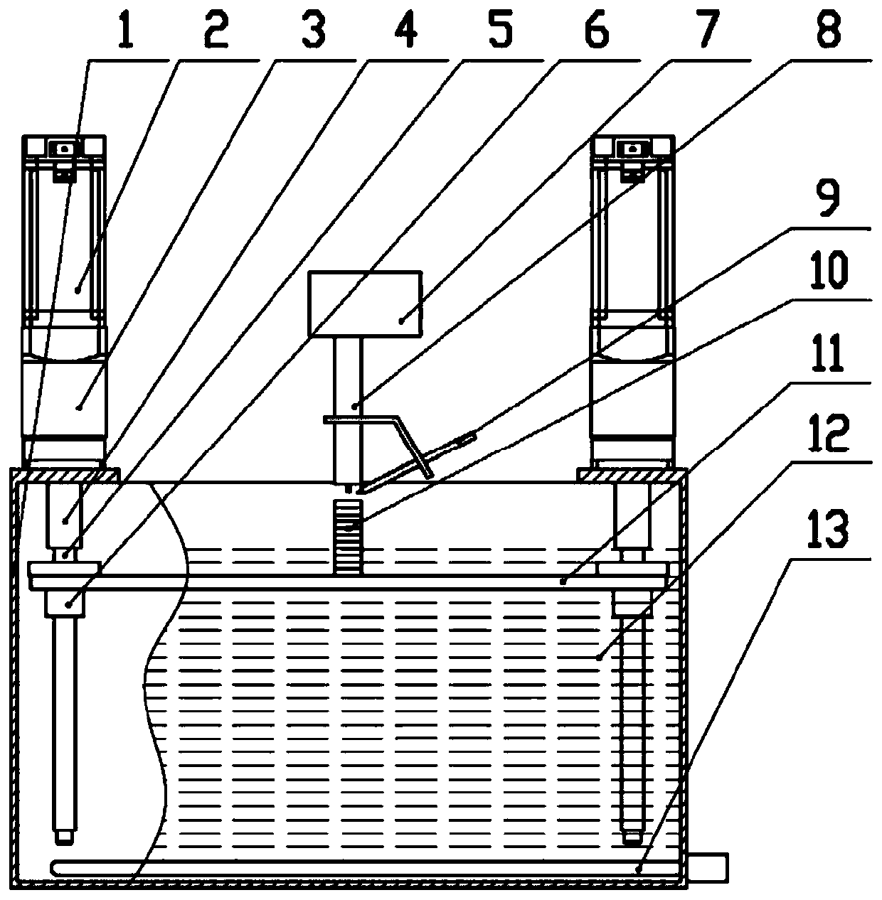
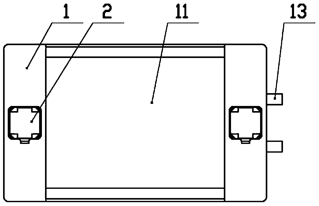
[0024] see Figure 1-2 As shown, the present invention provides a cooling device used in the arc printing additive manufacturing process. A driving mechanism is installed symmetrically above the cooling tank 1. The driving mechanism is connected through a coupling 4 and drives the lifting mechanism to move up and down in the cooling tank 1. Cooling liquid 12 is injected into the cooling tank 1, and the bottom of the cooling tank 1 is provided with a cooling coil 13, and the cooling coil 13 injects cooling water through a water pump, and the cooling water is used to take away the heat absorbed by the cooling liquid 12.

[0025] Further, the drive mechanism includes a servo motor 2, the lifting mechanism includes a lead screw 5 and a lifting base plate 11, the servo motor 2 is connected to the reducer 3, and the lower output shaft of the reducer 3 is connected to the lead screw 5 through a coupling 4 to drive the lead screw 5 rotates, the lead screw 5 passes through the lifting ...


PUM


Abstract

The invention belongs to the technical field of additional material manufacturing equipment, and particularly relates to a cooling device for the manufacturing process of an electric arc printing additional material. Two servo motors are fixed to the two sides of the upper side of a cooling tank correspondingly after being directly connected with a speed reducer. A lower output shaft of the speedreducer is connected with a lead screw through a coupler and drives the lead screw to rotate. A nut is fixed to a lifting base plate and connected with the lead screw through threads. The lead screw can drive the nut and the lifting base plate to rise or fall in the cooling tank when rotating. Cooling liquid is arranged in the cooling tank. A cooling coiled pipe is arranged at the bottom of the cooling tank. Cooling water is injected into the cooling coiled pipe through a water pump. Through the cooling of constant-temperature water of the cooling coiled pipe, the heat absorbed by the coolingliquid can be brought away in time, it is ensured that the cooling liquid is not solidified, the long-term electric arc printing work is ensured, meanwhile the temperature of the cooling liquid in thenext time of printing can be ensured, the cooling device has the advantages of being high in cooling efficiency and good in cooling effect, not influencing the existing structure properties of the product and the like, and the simple, rapid and efficient cooling in the manufacturing process of the electric arc printing additional material is realized.

Description

technical field [0001] The invention belongs to the technical field of additive manufacturing equipment, and in particular relates to a cooling device used in the arc printing additive manufacturing process. Background technique [0002] Arc printing additive manufacturing refers to the method of 3D printing in the form of surfacing welding using metal wire as the raw material and using the arc as the heat source. This method has the advantages of low raw material cost, high material utilization rate, high printing and forming efficiency, and high workpiece density. When using arc printing additive manufacturing, the workpiece needs to be printed on the prefabricated metal substrate. During the surfacing process, as the surfacing height continues to increase, it will cause heat accumulation inside the printed workpiece, and the natural cooling speed is slow, so that the printed The workpiece is easy to collapse and form a larger grain structure, which is not conducive to th...

Claims


Application Information

Patent Timeline
IPC IPC(8): B23K37/00B33Y40/00
CPCB23K37/003B33Y40/00
Inventor 张磊贾庆功张嘉马乐王锦群方向明王一帆杜亚宁张弛李扬扬王志杰张蕾
Owner XIAN JUNENG EQUIP TECH CO LTD
Learn More