Permanent-and-temporary combined retaining wall structure in urban water conservancy project and construction method of structure

A technology that combines water conservancy projects with permanent and immediate use. It is applied in water conservancy projects, underwater structures, sea area projects, etc. It can solve the problems of the existing revetment structure, the impact on the safety of bridge structures, and the low degree of comprehensive utilization, etc., and achieve comprehensive High degree of utilization, convenient construction, and reduced excavation land occupation

Pending Publication Date: 2020-04-21
浙江省水利水电勘测设计院有限责任公司
View PDF0 Cites 3 Cited by
  • Summary
  • Abstract
  • Description
  • Claims
  • Application Information

AI Technical Summary

Problems solved by technology

Due to the dense buildings around the project, the overall planning of the city or the limited scope of the land use red line, the traditional grading excavation occupies a large area, and it is inconvenient to construct when the surrounding site is cramped. , the enclosure structure only undertakes the function of temporary protection during construction. After the project is completed, it is generally dismantled or discarded. It does not double as a retaining wall structure, and the degree of c

Method used


Image

  • Permanent-and-temporary combined retaining wall structure in urban water conservancy project and construction method of structure
  • Permanent-and-temporary combined retaining wall structure in urban water conservancy project and construction method of structure
  • Permanent-and-temporary combined retaining wall structure in urban water conservancy project and construction method of structure

Examples


Example Embodiment

[0030] Example 1:

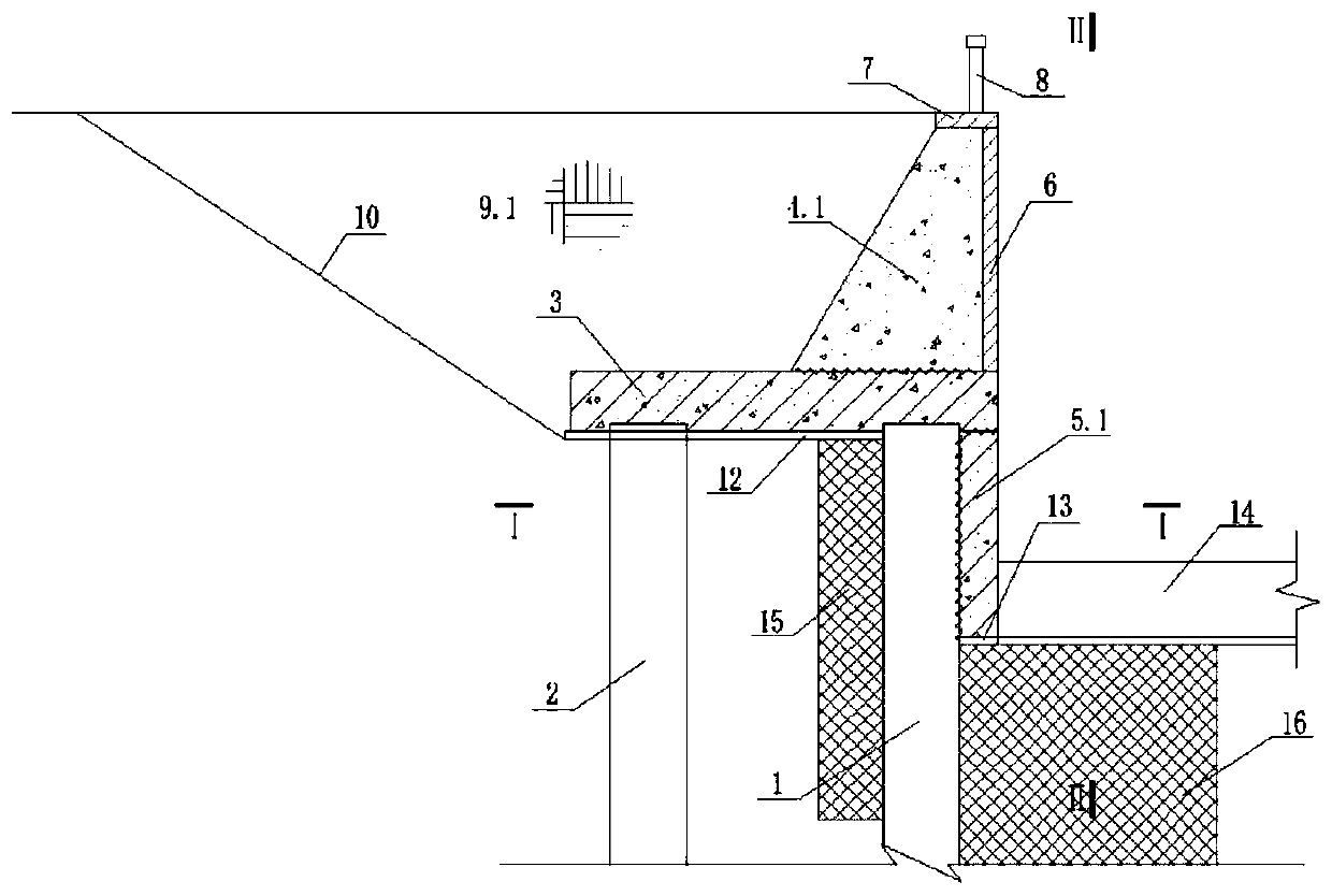
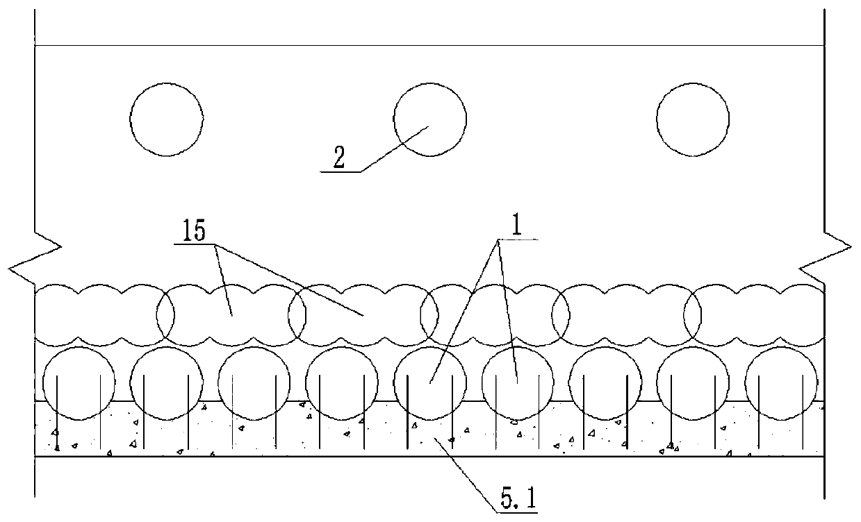
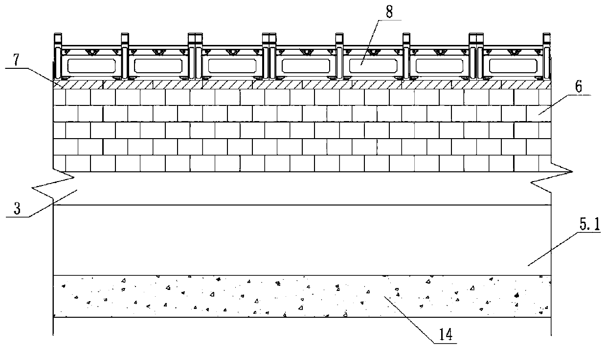
[0031] Such as Figure 1-Figure 3 As shown, the main frame structure of the retaining wall of the present invention includes the front row of reinforced concrete cast-in-place piles 1, the rear row of reinforced concrete cast-in-place piles 2, the reinforced concrete cap 3, the gravity retaining wall 4.1, the reinforced concrete baffle 5.1, and the front row Reinforced concrete cast-in-place piles 1 are arranged in close rows, the rear row of reinforced concrete cast-in-place piles 2 are arranged at intervals, and the reinforced concrete caps 3 are arranged on the pile tops of the front row of reinforced concrete cast-in-place piles 1 and the rear row of reinforced concrete cast-in-place piles 2, passing through the steel bars and the front row The reinforced concrete cast-in-place pile 1, the rear row of reinforced concrete cast-in-place piles 2 are connected as a whole to form a double-row pile enclosure structure, the gravity retaining wall 4.1 is connected ...

Example Embodiment

[0032] Example 2:

[0033] Such as Figure 4-Figure 6 As shown, the difference from Embodiment 1 is that in this embodiment, a semi-gravity retaining wall 4.2 is set to replace the gravity retaining wall 4.1 in Embodiment 1; a reinforced concrete L-shaped retaining wall 5.2 is set to replace the one in Embodiment 1. Reinforced concrete baffle 5.1, and add a row of additional reinforced concrete cast-in-place piles 11 on the side of the river. Reinforced concrete L-shaped retaining wall 5.2 is arranged on the top of the additional reinforced concrete cast-in-place pile 11 and the front row of reinforced concrete cast-in-place piles 1 on the water side , Below the reinforced concrete cap 3.

[0034] Such as Figure 1 to Figure 6 As shown, the construction methods of the retaining wall structure of the present invention provided in Examples 1 and 2 are as follows:

[0035] S1. Construct cement mixing piles and reinforced concrete cast-in-place piles on the river bank or dry land. The ...


PUM


Abstract

The invention discloses a permanent-and-temporary combined retaining wall structure in an urban water conservancy project and a construction method of the structure. The retaining wall structure comprises reinforced concrete cast-in-place piles, concrete mixing piles, reinforced concrete bearing platforms, a gravity type (semi-gravity type) retaining wall, reinforced concrete baffles or a reinforced concrete L-shaped retaining wall, wherein front-row reinforced concrete cast-in-place piles and rear-row reinforced concrete cast-in-place piles are arranged with the reinforced concrete cast-in-place piles, and the reinforced concrete bearing platforms are arranged at the tops of the reinforced concrete cast-in-place piles and combined with the front-row reinforced concrete cast-in-place pilesand the rear-row reinforced concrete cast-in-place piles to form a large rigid frame system double-row pile enclosure structure. According to the permanent-and-temporary combined retaining wall structure in the urban water conservancy project and the construction method of the structure, the excavation land occupation of the retaining wall can be effectively reduced, the comprehensive utilizationdegree is high, the structure can be directly connected with an existing building through the front-row and dense-row cast-in-place piles, the influence on the existing building is effectively reduced, the safety of the building is guaranteed, the double-row pile reinforced concrete bearing platforms can be used as platforms of a retaining wall dressed stone facing, construction is facilitated, the permanent retaining wall and a temporary enclosure structure are combined, and the engineering investment is saved.

Description

technical field [0001] The invention relates to a retaining wall structure and a construction method thereof, in particular to a permanently combined retaining wall structure and a construction method thereof in urban water conservancy projects connected with existing buildings. Background technique [0002] Retaining wall structures are often used in river courses, pump stations and sluice projects of urban water conservancy projects, and the following structural types are generally used: (1) gravity retaining wall; (2) semi-gravity retaining wall; (3) Cantilever retaining wall; (4) Buttress retaining wall; (5) Empty box retaining wall. In actual use, one or more types of retaining walls are selected according to factors such as the height of the retaining wall, the form of the foundation and the layout of the project. [0003] With the development of society and economy, the requirements for urban flood control and drainage are getting higher and higher, and many water co...

Claims


Application Information

Patent Timeline
IPC IPC(8): E02B3/06E02D29/02
CPCE02B3/066E02D29/02E02D29/0275
Inventor 余锦地姜惠明宋海娟
Owner 浙江省水利水电勘测设计院有限责任公司
Why Eureka
Try Eureka