
Leaked oil collecting and classifying device

A sorting device and oil technology, applied in the direction of liquid separation, separation method, general water supply saving, etc., can solve the problems of marine pollution, high energy consumption, high cost, etc., to improve the recovery of oil bodies, improve the separation effect, and reduce the cost of cleaning pollution low effect

Inactive Publication Date: 2020-04-21
ZHEJIANG OCEAN UNIV
View PDF6 Cites 1 Cited by
  • Summary
  • Abstract
  • Description
  • Claims
  • Application Information

AI Technical Summary

Problems solved by technology

However, the use of chemical agents may cause new pollution to the ocean, and the large-scale use of chemical agents will greatly increase the cost of cleaning up pollution, so this method of cleaning up pollution is not widely used
Physical methods usually use fences to prevent oil from spreading, and then use oil suction machines to absorb oil, or put adsorbents on the sea surface to absorb oil. This method is not effective and inefficient; there are also large-scale mechanical collection methods. The cost of the method is too high, the energy consumption is too large, and the collection efficiency is low

Method used


Image

  • Leaked oil collecting and classifying device
  • Leaked oil collecting and classifying device
  • Leaked oil collecting and classifying device

Examples


Embodiment 1

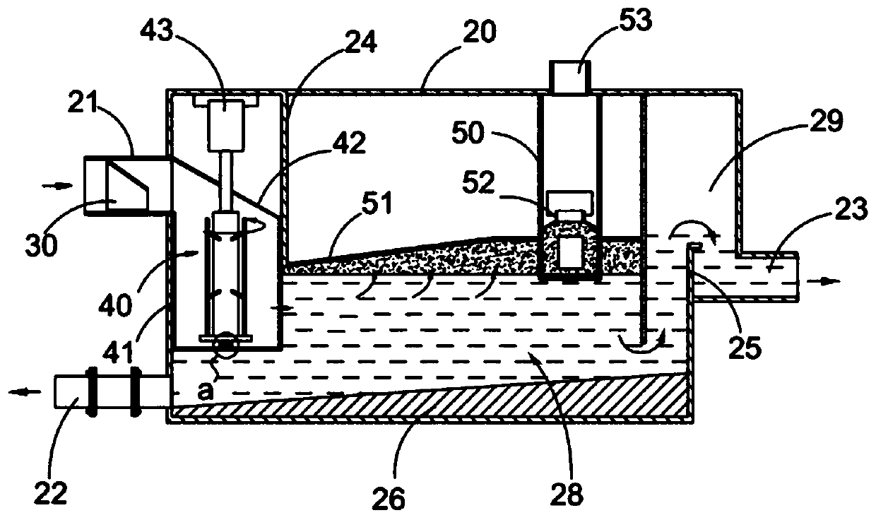
[0031] see figure 1 , 2 As shown in , 9, a leaking oil collection and classification device includes: a separation processing assembly 20, which is arranged on the water surface moving assembly 100, and the separation processing assembly 20 extracts the water surface oil through the external liquid suction power part 10 and the liquid transfer pipe 11 The liquid mixture, the separation processing assembly 20 includes a processing box, and one side of the processing box is provided with a mixed liquid inlet pipe 21 connected to the liquid transfer pipe 11, and at least two inlet guide sleeves 30 are arranged in the mixed liquid inlet pipe 21 to feed The two ports of the flow guide sleeve 30 are circular and have different sizes. The small end of the aperture is set to the end of the outlet direction of the oil-water mixture, and the end of the large aperture is set to the end of the flow direction of the oil-water mixture. 21 connected to the first oil-water separation chamber...

Embodiment 2

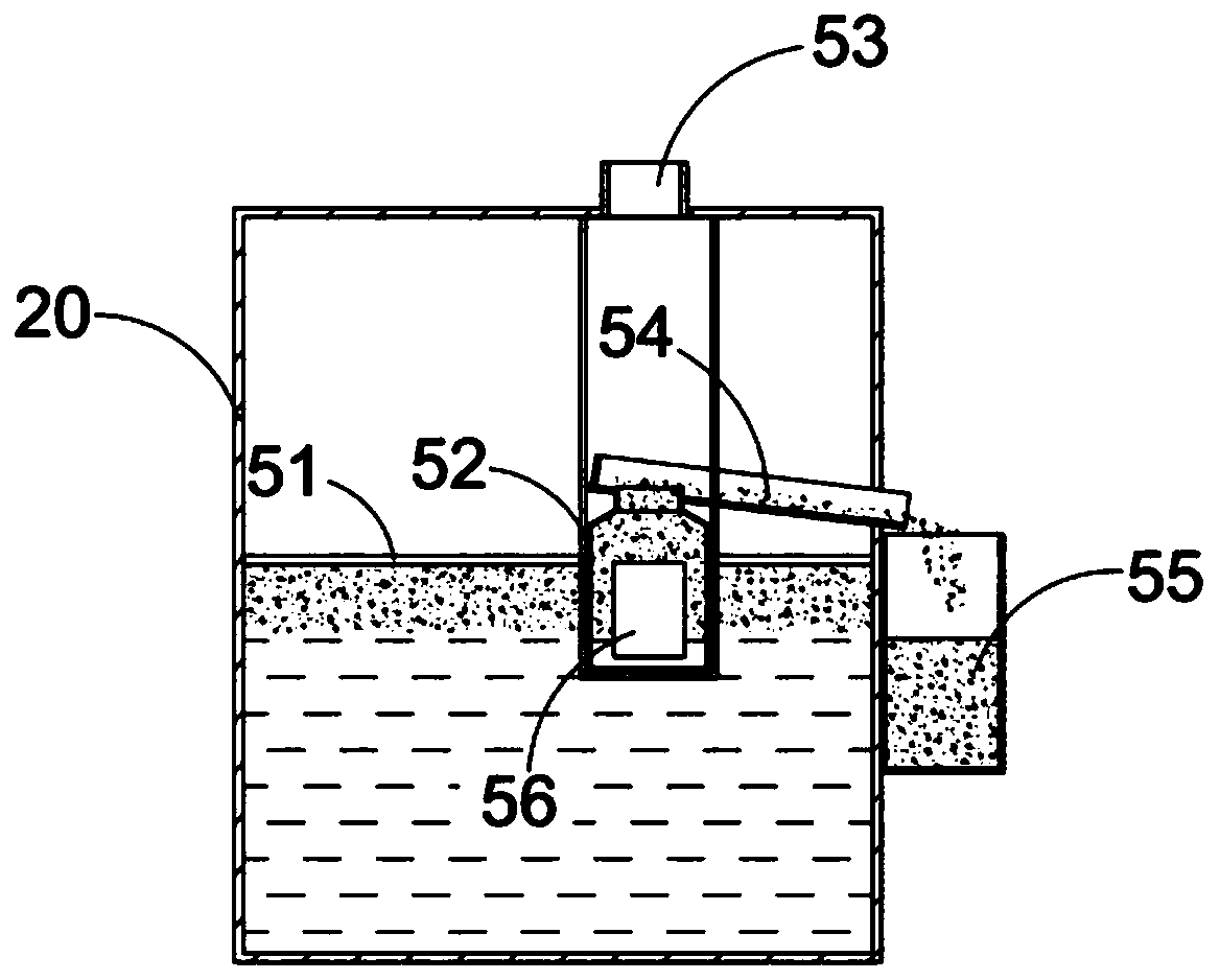
[0043] After an oil spill accident occurs, move the component 100 through the water surface, such as the hull loading the separation treatment component 20, and quickly sail to the oil spill sea area or water area to recover the leaked oil, and use the liquid suction power part 10, such as a high-power water pump to cooperate with the liquid transfer pipe 11 And the installed liquid suction sleeve 60 to extract the oil-water mixture on the surface of the water into the separation treatment assembly 20. After the oil-water mixture enters the separation treatment assembly 20, it goes through the first oil-water separation chamber for centrifugal treatment and the second oil-water separation. Chamber sedimentation treatment The separated crude oil is discharged to the oil collection container 55 through the oil discharge assembly 50 for unified collection, and the separated water body passes through the overflow plate body 25 and then is discharged from the separation treatment ass...

Embodiment 3

[0046] Spilled oil simulated collection test:

[0047] In order to avoid the test from polluting the environment, the test design is carried out in a water tank for simulation tests. The size of the water tank is: length x width x height = 3m x 1.5m x 1m; and the water tank is made of transparent glass for easy observation. The temperature of the water in the tank 23±1℃, water density ρ ω 986kg / m 3 , oil density ρ o 892kg / m 3 , the design leakage oil flow rate is 1m 3 / h.

[0048] Design four groups of experimental groups to carry out the oil collection test, which are experimental group 1, experimental group 2, experimental group 3, and experimental group 4. The water content of the oil collected by each experimental group is detected respectively, and the detection method is selected - the determination of the water content of crude oil Hugh coulometric titration (GB / T11146-2009).

[0049] Experimental group 1 selects the device of embodiment 1 of the present invention...


PUM


Abstract

The invention discloses a leaked oil collecting and classifying device, and belongs to the technical field of water surface oil stain cleaning. The leaked oil collecting and classifying device comprises a separation treatment assembly, a water surface oil-liquid mixing body is extracted by the separation treatment assembly through an external liquid suction power piece and an external liquid transfer pipe, the separation treatment assembly comprises a treatment box body, a mixed liquid inlet pipe connected with the liquid transfer pipe is arranged on one side of the treatment box body, at least two inflow guide sleeves are arranged in the mixed liquid inlet pipe, two ports of each inflow guide sleeve are round and different in size, the small-hole-diameter end and the oil-water mixed liquid outflow direction end are arranged, and the large-hole-diameter end and the oil-water mixed liquid inflow direction end are arranged, and a first oil-water separation chamber, a second oil-water separation chamber and a liquid discharge chamber are arranged in the treatment box body. By means of centrifugal separation and settling separation, oil particle membrane rupture is promoted, so that the oil particle coalescence effect is improved, the recovery amount of leaked crude oil is increased, it is guaranteed that floating oil with the oil particle size smaller than 100 micrometers is recovered, and environmental pollution and leakage loss caused by the leaked crude oil are reduced.

Description

technical field [0001] The invention belongs to the technical field of oil pollution cleaning on the water surface, and in particular relates to a device for collecting and classifying leaked oil. Background technique [0002] According to incomplete statistics from 1977 to 2000, there have been 156 accidents involving oil spills from computing vessels around the world. The oil leaked into the sea every year accounts for about 0.5% of the world's crude oil production, which has caused great harm to human life, ecological environment, and economic development. Bad influence. More famous accidents such as: In 1989, an oil tanker of Exxon Petroleum Company hit a rock and sank when it sailed into Prince William Port, Alaska, USA, causing tens of thousands of tons of crude oil to leak. In the end, the cost of rescue and compensation for the accident was as high as 8 billion US dollars. Another example is that in November 2002, the oil tanker Prestige ran aground and sank in the ...

Claims


Application Information

Patent Timeline
Patent Type & Authority Applications(China)
IPC IPC(8): E02B15/04B01D17/032B01D17/038B01D17/04
CPCB01D17/0214B01D17/0217B01D17/045E02B15/045Y02A20/204
Inventor 周佑霖田丽娜潘玉英舒舵杨啸峰
Owner ZHEJIANG OCEAN UNIV
Learn More