Intelligent chuck

A chuck, intelligent technology, applied in welding equipment, laser welding equipment, metal processing equipment and other directions, can solve the problems of high procurement cost, high labor intensity, large clamping mechanism, etc., to achieve simple and efficient on-site management, labor intensity The effect of reduction and transportation cost reduction

Pending Publication Date: 2020-04-24
何翔
View PDF0 Cites 1 Cited by
  • Summary
  • Abstract
  • Description
  • Claims
  • Application Information

AI Technical Summary

Problems solved by technology

The chuck device of the existing laser cutting machine or laser welding machine has the following technical problems: (1) The cylinder is used as the power source for the chuck to clamp the pipe. Since the cylinder is controlled by pneumatics, it belongs to fuzzy control, resulting in the pipe being out of order. When the diameter is different, due to the limitation of the stroke of the cylinder rod, the clamping force generated by the cylinder is inconsistent, which is not suitable for the digitalized precision machining laser cutting machine or laser welding machine; (2) for the different diameters Pipes require a series of clamping sleeves, which leads to a large number of clamping sleeves for a laser cutting machine or laser welding machine, which directly leads to a large inventory of clamping sleeves and takes up a lot of space on the site. High cost and complex on-site management; (3) When processing pipes with different outer diameters, the corresponding clamping sleeves need to be replaced continuously, resulting in a series of problems such as high labor intensity, inconvenient use, and low work efficiency; (4) Clamping The mechanism is bulky and can only be combined with a laser cutting machine or a laser welding machine in a split form. It is difficult to integrate with a laser cutting machine or a laser welding machine to form an integrated structure, and the equipment takes up a lot of space; (5) There are few clamping points, and It is difficult to expand the clamping point, it can only be used to clamp round pipes or square pipes, and it cannot be clamped for special-shaped pipes

Method used


Image

  • Intelligent chuck
  • Intelligent chuck
  • Intelligent chuck

Examples


Embodiment Construction

[0052] The present invention and its beneficial technical effects will be further described in detail below in conjunction with the accompanying drawings and preferred embodiments.

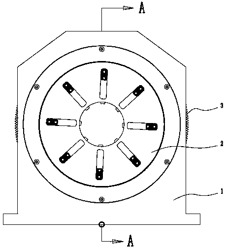
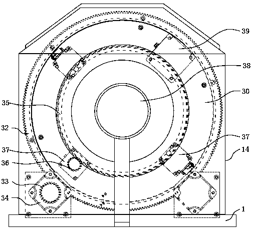
[0053] see Figure 1~Figure 20 , the intelligent chuck preferably implemented in the present invention includes a fixed base 1, a clamping mechanism 2 for clamping pipes, a driving mechanism 3 for driving the clamping mechanism 2 to rotate, the driving mechanism 3 is arranged on the rear side of the fixing base 1, and clamps The mechanism 2 is arranged on the front side of the fixed base 1; its characteristics are:

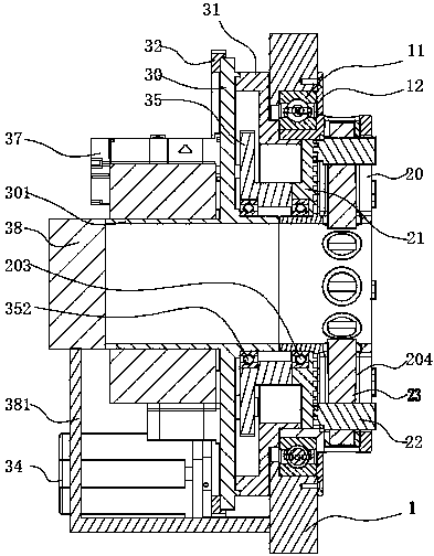
[0054] see figure 2 , the fixed base 1 is provided with a chuck mounting hole 5 through front and back, and the chuck mounting hole 5 is embedded with a chuck bearing 11;

[0055] see figure 2 , the clamping mechanism 2 includes a rotary chuck 20, a jaw locking disc 21, jaws 22, and a workpiece clamping head 24;

[0056] see figure 2 , the drive mechanism 3 includes a motor mo...


PUM


Abstract

The invention discloses an intelligent chuck. A driving mechanism of the intelligent chuck is divided into two drivers for driving clamping mechanisms to work, wherein one driver is a chuck rotating driver which comprises an external disk servo motor, an external small spur gear, an external large gear, a motor mounting disk, and a chuck rotating sleeve and is used for driving a rotating chuck torotate; and the other driver is a locking disk rotating driver which comprises an internal disk servo motor, an internal small gear and an internal big gear and is used for driving clamping jaw locking disks to rotate. The internal disk servo motor of the locking disk rotating driver is used for driving the clamping jaw locking disks to rotate; and the clamping jaws linearly slides through the rotary movement of the clamping jaw locking disks, so that workpiece clamping heads are driven by the clamping jaws to inwards clamp a pipe. The intelligent chuck has the advantages that the internal disk servo motor is used as a power source of the chuck for clamping the pipe to realize the digital control; the intelligent chuck is suitable for various types of pipes with different outer diameters;the clamping force of the clamping jaws has good consistency; a series of matched shaft sleeves are not needed; the space is saved; the working efficiency is improved; and the equipment cost is reduced.

Description

technical field [0001] The invention relates to a laser cutting machine or a laser welding machine, in particular to a chuck used for a laser cutting machine or a laser welding machine. Background technique [0002] In existing laser cutting machines or laser welding machines, in order to ensure processing accuracy and processing quality, a structure in which the pipe material is rotated and the cutter is only used for feeding motion is usually adopted. Among them, in order to fix the pipe, the laser cutting machine or laser welding machine uses a chuck device to clamp the pipe. The chuck device includes a fixed seat, a clamping mechanism for clamping the pipe, and a driving mechanism for driving the clamping mechanism to rotate; the clamping The mechanism includes a chuck, several sets of clamping sleeves adapted to pipes of different calibers, and an air cylinder that drives the clamping sleeves to clamp the pipes. The chuck device of the existing laser cutting machine or...

Claims


Application Information

Patent Timeline
Patent Type & Authority Applications(China)
IPC IPC(8): B23K26/70
CPCB23K26/70B23K26/702
Inventor 何翔
Owner 何翔
Why Eureka
Try Eureka