Pipeline defect phonon diagnostic system and realization method

A diagnostic system and phonon technology, applied in pipeline systems, mechanical equipment, gas/liquid distribution and storage, etc., can solve problems such as difficult defect detection, economic loss, and inability to monitor material defects in time

Active Publication Date: 2020-04-24
BEIJING UNIV OF TECH
View PDF9 Cites 3 Cited by
  • Summary
  • Abstract
  • Description
  • Claims
  • Application Information

AI Technical Summary

Problems solved by technology

Non-destructive testing is a non-contact testing technology, which mainly uses the physical or chemical reactions of light, heat, magnetism and electricity in the equipment to obtain the status information of the equipment. The type of defect is sensitive, it is difficult to find defects in the microscopic state of the material, it is not suitable for the detection of all defect types, and the operation cost of comprehensive detection of trench

Method used


Image

  • Pipeline defect phonon diagnostic system and realization method
  • Pipeline defect phonon diagnostic system and realization method
  • Pipeline defect phonon diagnostic system and realization method

Examples


Embodiment 1

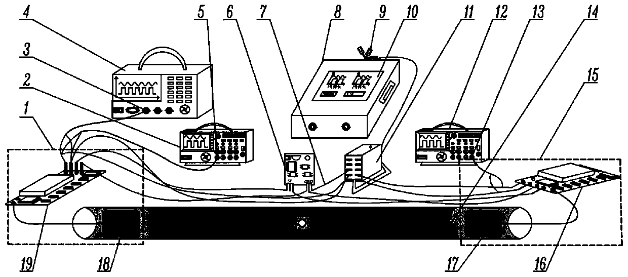
[0072] The application possibilities of the digital phonon diagnostic detection system will be disclosed using the following examples. Such as figure 1 As shown, the described experimental device system includes: phonon emission module 1, oscilloscope 2, signal generator 4, power supply board 6, data signal line 7, industrial computer 8, USB interface 9, liquid crystal display 10, acquisition card 11 , an oscilloscope 12, a 3m steel pipeline 14, a phonon receiving module 15, a phonon receiving probe 16, a phonon signal receiving end 17, a phonon signal transmitting end 18, and a phonon emitting probe 19.

[0073] In order to detect a 3m buried steel pipeline with a small hole in the middle and open at both ends, the following steps will be followed:

[0074] Step 1, the phonon emission probe 19 in the phonon emission module 1 is paired with the phonon signal emission end 18, and the phonon reception probe 16 in the phonon reception module 15 is paired with the phonon signal r...

Embodiment 2

[0086] In engineering practice, there are blind plates fixed by bolts on both sides of the pipeline, which are used to input fluid, such as figure 1 As shown, in the experiment, the 8m side with a blind hole defect is taken as an example. The blind plate on one side is opened and water is poured in to simulate the fluid transmission. The specific steps are as follows:

[0087] Step 1, the phonon emission probe 19 in the phonon emission module 1 is paired with the phonon signal emission end 18, and the phonon reception probe 16 in the phonon reception module 15 is paired with the phonon signal reception end 17;

[0088] Step 2, placing a pair of phonon emitting modules 1 and phonon receiving modules 15 on the two ends of the outer surface of the 8m-long pipeline 14, so that the phonon signal transmitting end 18 and the phonon signal receiving end 17 are at the same horizontal line;

[0089] Step 3, use the data signal line 7 to connect the red line of the output channel 3 of th...


PUM


Abstract

The invention discloses a pipeline defect phonon diagnostic system and a realization method. The digital phonon diagnostic detection system involves a phonon emission module, a phonon receiving module, an oscilloscope, a signal generator, an industrial computer, an acquisition card and a power supply plate device, wherein the phonon emission module comprises a phonon emission probe and a phonon signal emission end, and the phonon receiving module comprises a phonon receiving probe and a phonon signal receiving end. In the method, a modulator with a GFSK modulation mode is integrated on the phonon emission probe, a signal provided by the signal generator is modulated to 433 MHz, and is acted on a to-be-detected pipeline through the phonon signal emission end to be transmitted to the phononreceiving end, the phonon emission probe utilizes a demodulation module to adopt GFSK to demodulate the signal, the signal is transmitted to the industrial computer with the acquisition card through adata signal line, and signal acquisition is completed. The pipeline defect phonon diagnostic system can realize the defect detection of the pipeline, save the cost, find and locate the defect in time, is a new branch in the field of non-destructive examination, and has a wide application prospect.

Description

technical field [0001] The invention relates to information collection, electromagnetic carrier, solid physics, phonon theory, non-destructive testing, signal processing and other multidisciplinary fields, in particular to a digital phonon diagnosis and detection system, which can be used for defect detection of steel pipelines, especially Crossing the pipeline belongs to the new field of non-destructive testing of special equipment. Background technique [0002] At present, the detection technologies for pipeline defects mainly include external detection and internal detection. The external inspection method is mainly based on manual inspection. For large-scale equipment, the inspection is difficult and the process is complicated, and it is not conducive to discovering internal cracks, slag inclusions, pores and other welding defects in the pipeline, as well as microscopic cracks caused by stress concentration and corrosion. Therefore, regular inspection of the pipeline is...

Claims


Application Information

Patent Timeline
IPC IPC(8): F17D5/06
CPCF17D5/06
Inventor 王新华宋艳伟赵以振谷雅萍陈迎春帅义
Owner BEIJING UNIV OF TECH
Why Eureka
Try Eureka