Gas treatment system and method

A technology of gas dust removal and dust removal system, which is used in exhaust gas treatment, electronic control of exhaust gas treatment device, charging system, etc.

Inactive Publication Date: 2020-04-28
SHANGHAI BIXIUFU ENTERPRISE MANAGEMENT CO LTD
View PDF0 Cites 14 Cited by
  • Summary
  • Abstract
  • Description
  • Claims
  • Application Information

AI Technical Summary

Problems solved by technology

At the same time, the present invention discovers new problems existing in the existing ionization dust removal technology through research, and solves them through a series of technical means

Method used


Image

  • Gas treatment system and method
  • Gas treatment system and method
  • Gas treatment system and method

Examples


Embodiment 1

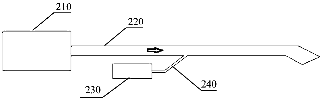
[0756] like Figure 5 As shown, the gas dust removal system includes a water removal device 207 and an electric field device. The electric field device includes a dust removal electric field anode 10211 and a dust removal electric field cathode 10212, and the dust removal electric field anode 10211 and the dust removal electric field cathode 10212 are used to generate an ionization and dust removal electric field. The water removal device 207 is used to remove liquid water before the entrance of the electric field device. When the gas temperature is lower than 100°C, the water removal device removes liquid water in the gas. The water removal device 207 is an electrocoagulation device. The direction of the arrow in the figure is the gas flow direction.

[0757] A gas dedusting method, comprising the following steps: when the gas temperature is lower than 100°C, removing liquid water in the gas, and then ionizing dust removal, wherein the liquid water in the gas is removed by e...

Embodiment 2

[0759] like Image 6 As shown, the gas dust removal system includes an oxygen supply device 208 and an electric field device. The electric field device includes a dust removal electric field anode 10211 and a dust removal electric field cathode 10212, and the dust removal electric field anode 10211 and the dust removal electric field cathode 10212 are used to generate an ionization and dust removal electric field. The oxygen supply device 208 is used to add gas including oxygen before the ionization and dust removal electric field. The oxygen supply device 208 adds oxygen by introducing outside air, and the oxygen supply amount is determined according to the content of gas particles. The direction of the arrow in the figure is the flow direction of the gas including oxygen added by the oxygen supplement device.

[0760] A gas dedusting method, comprising the following steps: adding gas including oxygen before the ionization dedusting electric field, performing ionization dedu...

Embodiment 3

[0763] The gas treatment system in this embodiment further includes a gas treatment device, and the gas treatment device is used for treating waste gas to be discharged into the atmosphere.

[0764] see Figure 7 , is a schematic structural diagram of a gas processing device in an embodiment. like Figure 7 As shown, the gas treatment device 102 includes an electric field device 1021, an insulation mechanism 1022, an air uniform device, a water filter mechanism and a gas ozone mechanism.

[0765] The water filter mechanism in the present invention is optional, that is, the exhaust gas dust removal system provided by the present invention may or may not include a water filter mechanism.

[0766] The electric field device 1021 includes a dust removal electric field anode 10211 and a dust removal electric field cathode 10212 arranged in the dust removal electric field anode 10211, an asymmetric electrostatic field is formed between the dust removal electric field anode 10211 an...


PUM


Abstract

The invention provides a gas treatment system and method. The gas treatment system comprises a gas dedusting system and a gas ozone purification system. The gas dedusting system comprises a dedustingsystem inlet, a dedusting system outlet and an electric field device. The gas ozone purification system comprises a reaction field for the mixed reaction of an ozone stream and a gas stream. The gas treatment system disclosed by the invention can effectively remove particulate matters in gas and has a better gas purification treatment effect.

Description

technical field [0001] The invention belongs to the field of environmental protection and relates to a gas processing system and method. Background technique [0002] The air is layered and covers the earth's surface. It is transparent, colorless and odorless. It is mainly composed of nitrogen and oxygen, which has an important impact on human survival and production. With the continuous improvement of people's living standards, people have gradually realized the importance of air quality. In the prior art, air dust removal is usually carried out by means of a filter screen or the like. However, the dust removal effect of this method is unstable, the energy consumption is large, and it is easy to cause secondary pollution. [0003] Another kind of gas, such as the exhaust gas formed by combustion, usually contains a large amount of pollutants, and the direct discharge of such gas into the atmosphere will cause serious pollution to the environment. Therefore, the gas needs...

Claims


Application Information

Patent Timeline
Patent Type & Authority Applications(China)
IPC IPC(8): B03C3/011B03C3/017B03C3/06B03C3/36B03C3/41B03C3/47B03C3/49B03C3/62B03C3/34F02M35/02F02M35/08F02M35/022F01N3/01F01N3/00F01N3/08F01N13/14F01N9/00F01N3/32F01N3/05F01N5/02F02B41/00
CPCB03C3/011B03C3/017B03C3/06B03C3/363B03C3/41B03C3/47B03C3/49B03C3/62B03C3/34F02M35/0217F02M35/08F02M35/0216F02M35/0218F02M35/0226F02M35/0223F02M35/088F01N3/01F01N3/005F01N3/0842F01N3/0871F01N3/0828F01N13/14F01N9/00F01N3/32F01N3/05F01N5/02F02B41/00Y02T10/12Y02T10/40Y02A50/2351B03C3/28B03C3/09B03C3/0175B03C2201/08B03C2201/30F01N3/30F01N2900/1804Y02A50/20B03C3/368
Inventor 唐万福段志军王大祥邹永安奚勇
Owner SHANGHAI BIXIUFU ENTERPRISE MANAGEMENT CO LTD
Why Eureka
Try Eureka