
Magnetic gear speed-regulating permanent-magnet synchronous traction machine

A technology of synchronous traction machines and magnetic gears, applied in the field of traction machines, can solve the problems of large overall weight, large stator size, and large number of windings, etc., to reduce volume and weight, reduce longitudinal length, and directly transmit torque Effect

Pending Publication Date: 2020-04-28
GUANGDONG WINONE ELEVATOR
View PDF1 Cites 0 Cited by
  • Summary
  • Abstract
  • Description
  • Claims
  • Application Information

AI Technical Summary

Problems solved by technology

[0004] 1. The size of the stator is large, and the number of windings that need to be used is large, and the amount of enameled wire used is large, resulting in high material costs;
[0005] 2. The transmission between the magnetic gear rotor, the traction wheel and the main shaft is through a flat key, all of which need to occupy a relatively large depth dimension, resulting in a large size and a large overall weight of the overall traction machine, which is not convenient for manufacturing and processing And maintenance

Method used


Image

  • Magnetic gear speed-regulating permanent-magnet synchronous traction machine
  • Magnetic gear speed-regulating permanent-magnet synchronous traction machine
  • Magnetic gear speed-regulating permanent-magnet synchronous traction machine

Examples


Embodiment Construction

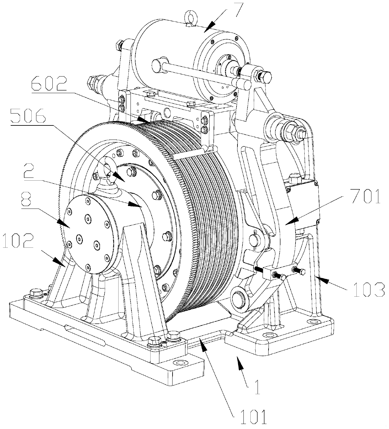
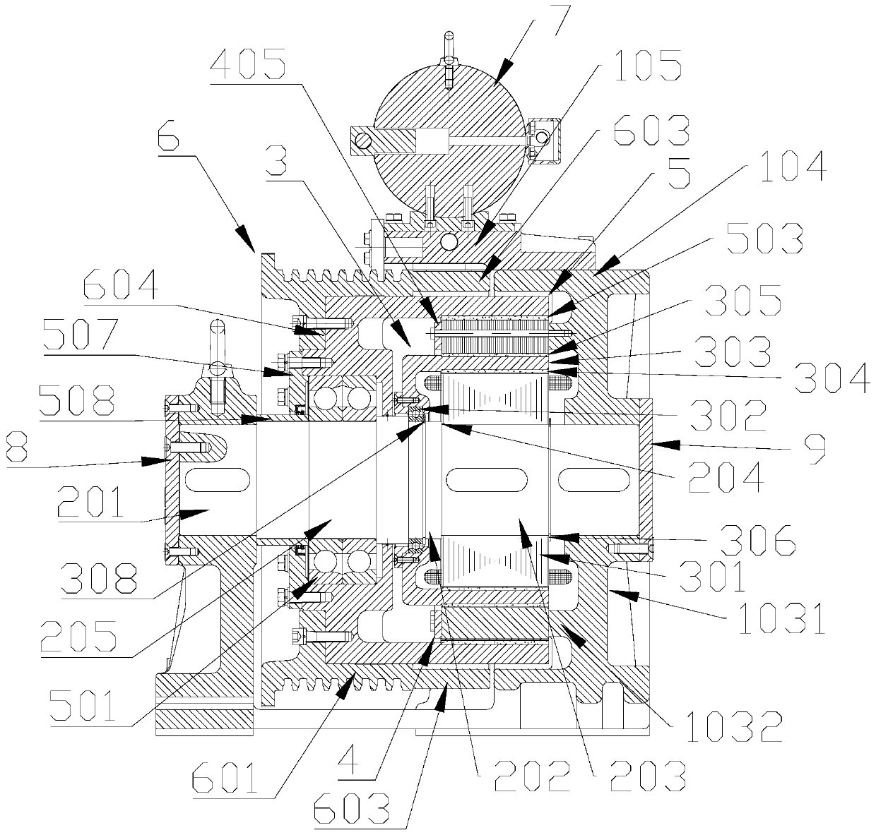
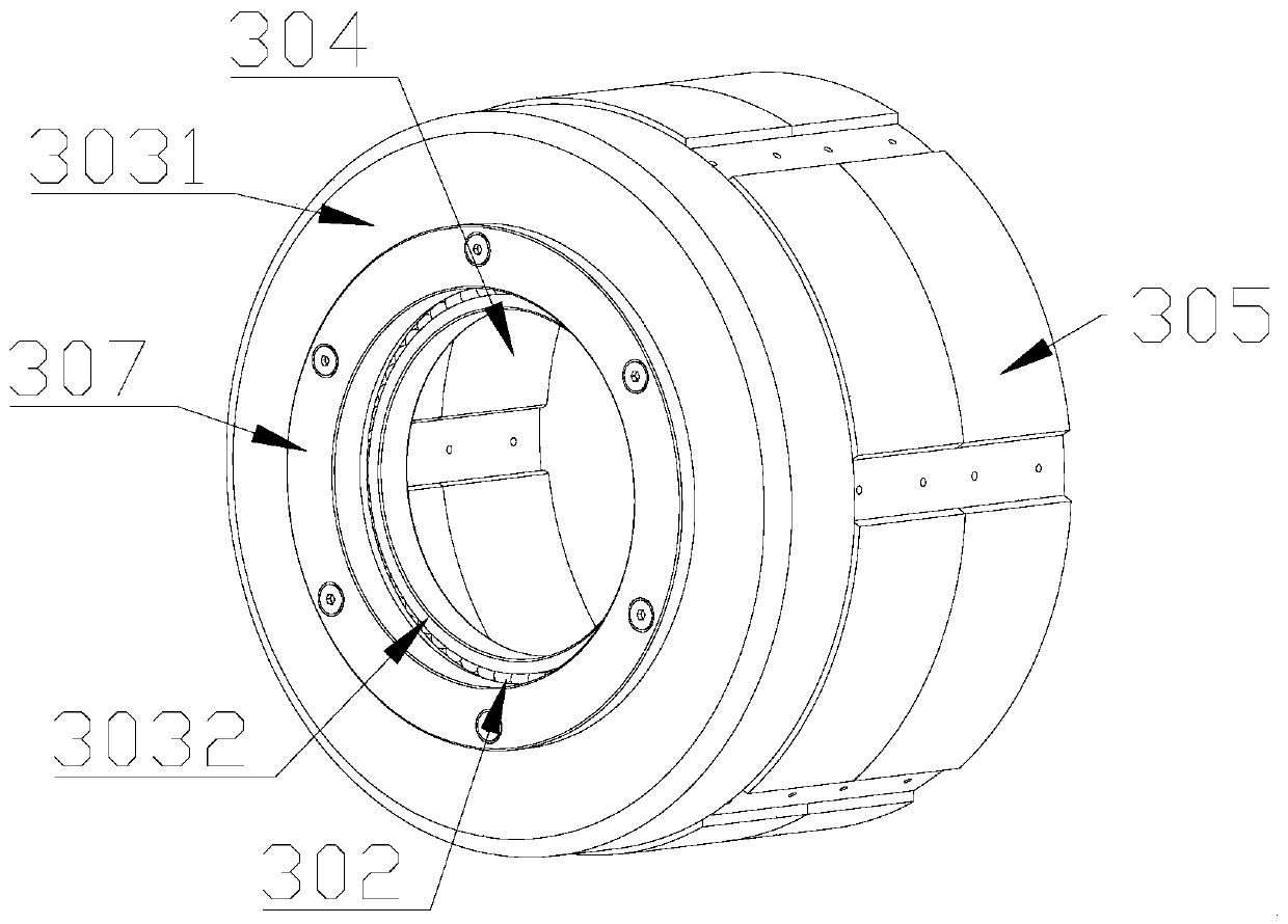
[0026] Such as Figure 1 - Figure 1 As shown, the magnetic gear speed-regulating permanent magnet synchronous traction machine of this embodiment includes:

[0027] The base 1 has a bottom support 101 and a front support 102 and a rear support 103 on the bottom support 101; the base is the same as the existing base, there are several main combinations, one is the bottom support , the front bracket and the rear bracket are independent parts, which are fixed together by fasteners. The other structure is integral casting, and the bottom support body, front bracket and rear main frame are integrated structures; there is also a front bracket. Or one of the parts of the rear bracket is cast together with the bottom support body to form an integrated structure, and then the other part is a separate part, which is fixed with the other two components by fasteners to form an integrated structure for carrying the drag The basis of each functional component of the engine.

[0028] The m...


PUM


Abstract

The invention relates to a traction machine, in particular to a magnetic gear speed-regulating permanent-magnet synchronous traction machine. The traction machine comprises a base, a main shaft, an outer rotor motor assembly, a magnetism adjusting iron core and a magnetism adjusting outer rotor, wherein the main shaft is arranged on the base, and the outer rotor motor assembly is provided with anouter rotor motor stator fixed on the main shaft and an outer rotor motor rotor arranged on the outer side of the outer rotor motor stator and arranged on the main shaft through a first bearing; and the magnetism adjusting iron core is arranged on the outer side of the outer wall of the outer rotor motor rotor, and the magnetism adjusting outer rotor is arranged on the outer side of the outer circumference of the magnetism adjusting iron core. According to the magnetic gear speed-regulating permanent-magnet synchronous traction machine, the motor and a magnetic gear are both of an outer rotorstructure, so that the size of the stator is reduced, and the use of an enameled wire is reduced; and meanwhile, the mandrel only plays a role of bearing and mounting, does not participate in torque transmission, and the torque output by the motor is directly transmitted to a traction wheel through the magnetic gear rotor, so that the torque transmission is more direct, the longitudinal length ofthe main shaft is reduced, and the overall size and weight are reduced.

Description

technical field [0001] The invention relates to a traction machine, in particular to a magnetic gear speed regulating permanent magnet synchronous traction machine. Background technique [0002] The traction machine is the main power output device for load traction. The common traction machine generally drives the main shaft to rotate through the rotor and then transmits the torque to the traction sheave, thereby driving the wire rope to output the traction force. With the development of modulated magnetic gears, some magnetic gear traction machines that are driven by the combination of magnetic gears and permanent magnet motors have appeared on the market. This type of traction machine is mainly suitable for traction machines with low speed and high torque output. . [0003] The existing permanent magnet synchronous traction machine with magnetic gear speed regulation generally includes a composite structure composed of a motor assembly, a magnetic core and a magnetic gear...

Claims


Application Information

Patent Timeline
IPC IPC(8): B66B11/04H02K1/27H02K21/22
CPCB66B11/043H02K21/22H02K1/2786H02K2213/03
Inventor 邓轶华杜秋张军锋麦志添
Owner GUANGDONG WINONE ELEVATOR
Learn More