
Method for identifying void defects of concrete-filled steel tube member based on infrared thermal imaging

A technology of steel pipe concrete and infrared thermal imaging, which is applied in the field of building material detection, can solve the problems that the hollow part cannot be detected by ultrasonic, and achieve the effects of low test cost, saving manpower and material resources, and easy operation

Pending Publication Date: 2020-04-28
ZHEJIANG UNIV +2
View PDF0 Cites 4 Cited by
  • Summary
  • Abstract
  • Description
  • Claims
  • Application Information

AI Technical Summary

Problems solved by technology

But its limitations are also obvious: the shape, size, material composition and surface roughness of the test piece have a great influence on the feasibility of ultrasonic testing; when making qualitative and quantitative analysis of the defects of the test components, it is necessary for the testing personnel to have rich experience. Based on experience; in order for the ultrasonic wave to enter the specimen effectively, a couplant must be used; when there is a hollow defect in the CFST, the hollow part cannot be tested by ultrasonic

Method used


Image

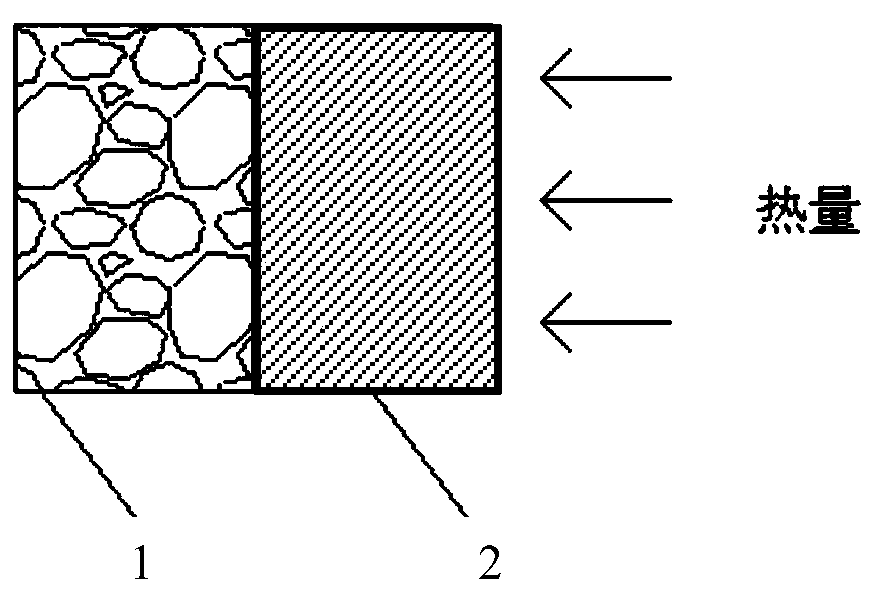
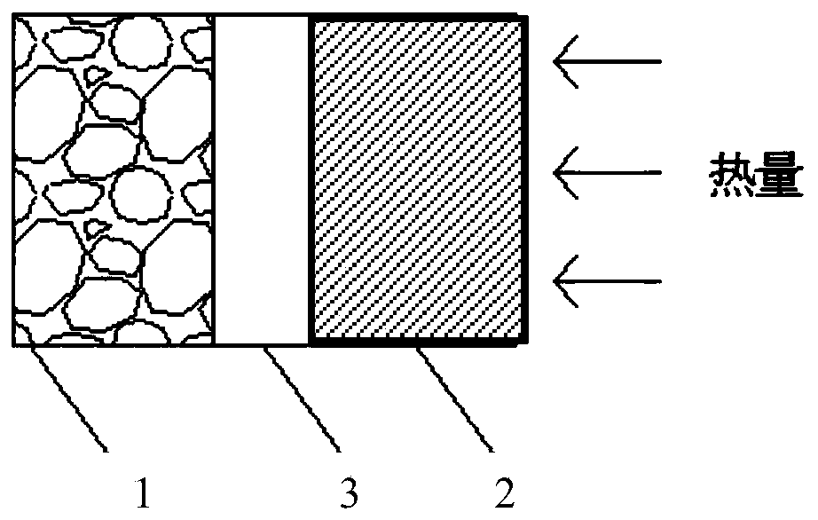
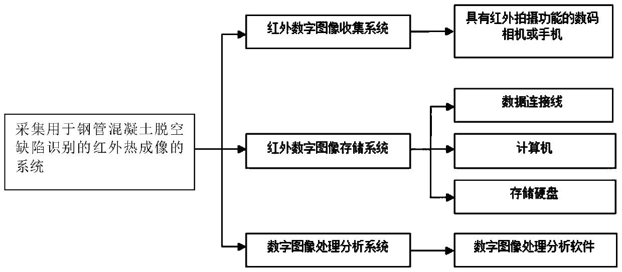
  • Method for identifying void defects of concrete-filled steel tube member based on infrared thermal imaging
  • Method for identifying void defects of concrete-filled steel tube member based on infrared thermal imaging
  • Method for identifying void defects of concrete-filled steel tube member based on infrared thermal imaging

Examples


Embodiment Construction

[0056] First of all, it needs to be explained that the present invention relates to infrared image temperature identification and calculation based on the identification result, and is an application of computer technology in the field of information security technology. During the implementation of the present invention, the application of multiple software function modules will be involved. The applicant believes that, after carefully reading the application documents and accurately understanding the realization principle and purpose of the present invention, combined with existing known technologies, those skilled in the art can fully implement the present invention by using their software programming skills. The aforementioned software functional modules include but are not limited to: infrared digital image processing software, digital image processing and analysis system, etc. All mentioned in the application documents of the present invention belong to this category, and...


PUM

PropertyMeasurementUnit
Thicknessaaaaaaaaaa

Abstract

The invention relates to the technical field of building material detection and aims at providing a method for identifying void defects of a concrete-filled steel tube member based on infrared thermalimaging. The method comprises the following steps: heating a to-be-measured area of a concrete-filled steel tube member through a heating device, shooting an image of the surface of a test piece, carrying out processing and analyzing through infrared digital image processing software, and calculating the temperature distribution gradient of the surface of the concrete-filled steel tube member bycomparing and analyzing temperature distribution rules of a heating area and a non-heating area; and further determining the range of the concrete-filled steel tube void area according to the temperature distribution gradient, and identifying the boundary of the concrete-filled steel tube void area. According to the method, the boundary of the void defect of the concrete-filled steel tube component is identified by adopting a temperature change rate method, so that the method has repeatability; and a test result is not influenced by human factors. The method is simple and convenient to operate, the test equipment can select different existing commercial instruments according to test precision requirements, so that manpower and material resources are saved, and the test cost is low.

Description

technical field [0001] The invention belongs to the technical field of building material detection, and in particular relates to a method for identifying void defects of steel pipe concrete components based on infrared thermal imaging. Background technique [0002] The concrete-filled steel tube structure is a new type of composite structure, which has the advantages of high bearing capacity and convenient construction, and is widely used in large-scale construction projects. In recent years, great progress has been made in theoretical research and engineering application of CFST structures in my country. In terms of theoretical research, our country has carried out in-depth research on the mechanical properties, shrinkage and creep, fire resistance and earthquake resistance of CFST members, and achieved phased research results. The relevant specifications of CFST structures have been gradually improved; In terms of application, CFST structures are developing in the directi...

Claims


Application Information

Patent Timeline
IPC IPC(8): G01N25/72
CPCG01N25/72
Inventor 陈劲王彬陈禾肖锋姚康伟田野
Owner ZHEJIANG UNIV
Learn More