Supercharge Your Innovation With Domain-Expert AI Agents!

Method for analyzing magnetic field radiation emission of power conversion unit by using finite elements

A conversion unit and radiation emission technology, applied in the direction of output power conversion devices, electrical components, design optimization/simulation, etc., can solve the problems of wide coverage frequency range, large amount of calculation, complex emission mechanism, etc., and reduce the scale of the model and calculation difficulty, reduce R&D costs, and improve analysis efficiency

Active Publication Date: 2020-04-28
NO 719 RES INST CHINA SHIPBUILDING IND
View PDF7 Cites 0 Cited by
  • Summary
  • Abstract
  • Description
  • Claims
  • Application Information

AI Technical Summary

Problems solved by technology

[0005] Due to the complexity of the interference source and emission mechanism of magnetic field radiation emission, the wide coverage frequency range, and the difficulty of accurate mathematical modeling and characterization, the current methods and data related to the analysis and simulation of magnetic field radiation emission are very limited; commercial finite element analysis software is used for the full three-dimensional structure The method of transient magnetic field simulation, the model is complex, the amount of calculation is large, and the efficiency is low, so it is difficult to quickly and effectively simulate the influence of the commutation process of the power conversion unit

Method used


Image

  • Method for analyzing magnetic field radiation emission of power conversion unit by using finite elements
  • Method for analyzing magnetic field radiation emission of power conversion unit by using finite elements
  • Method for analyzing magnetic field radiation emission of power conversion unit by using finite elements

Examples


Embodiment Construction

[0032] The technical solutions of the present invention will be described in more detail below in conjunction with the accompanying drawings, and the present invention includes but not limited to the following embodiments.

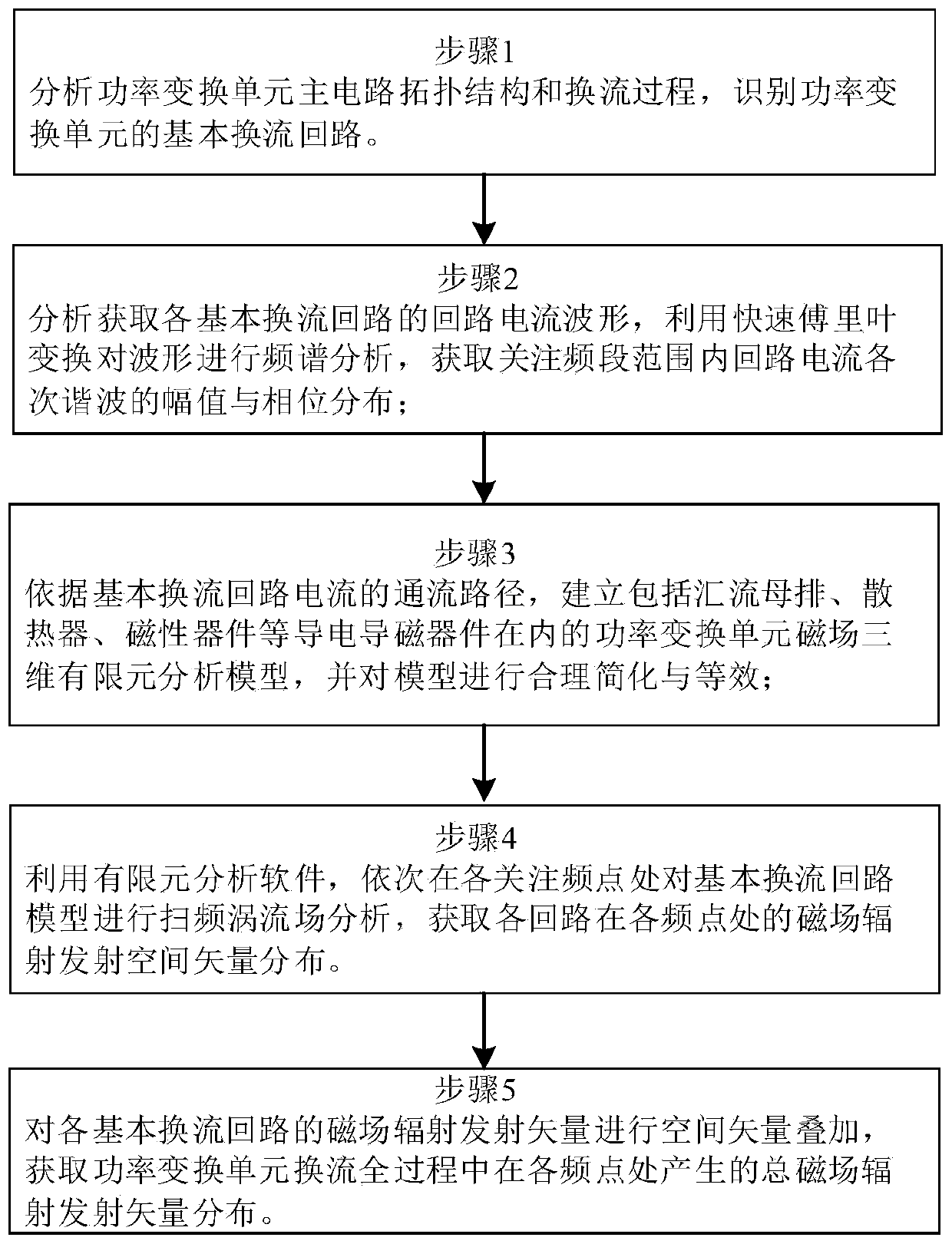
[0033] see figure 1 It shows a flow chart of a method for analyzing the magnetic field radiation emission of a power conversion unit by using finite elements according to an embodiment of the present invention. The present invention includes the following steps:

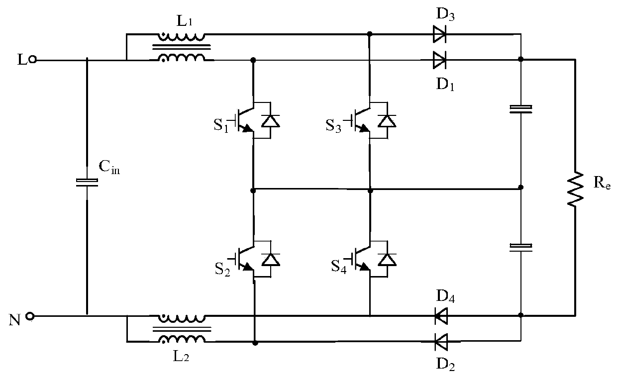
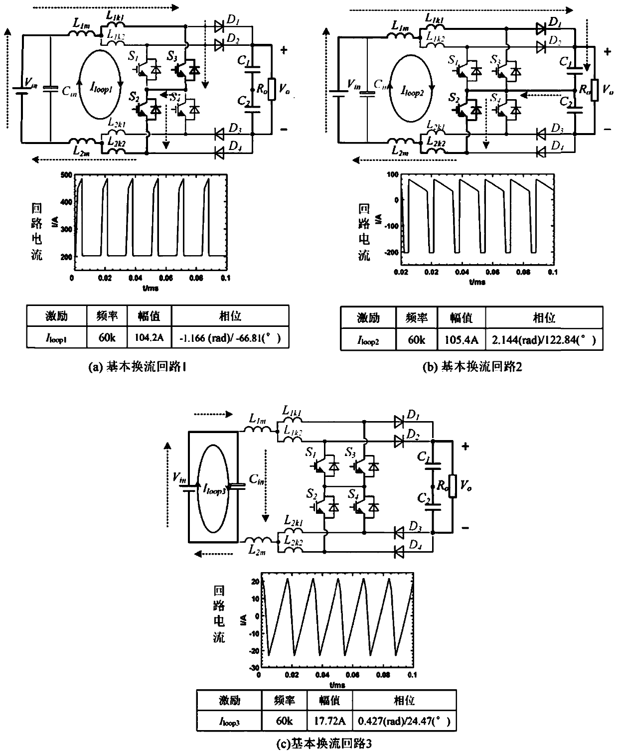
[0034] Step 1: Analyze the main circuit topology and commutation process of the power conversion unit, and identify the basic commutation circuit of the power conversion unit

[0035] Step 2: Use the circuit analysis method to obtain the circuit current waveform of each basic commutation circuit under the analysis condition, and use the fast Fourier transform to perform spectrum analysis on the waveform to obtain the amplitude of each harmonic of the circuit current within the frequency range of ...


PUM


Abstract

The invention discloses a method for analyzing magnetic field radiation emission of a power conversion unit by using a finite element. The method comprises the following steps: identifying a basic commutation loop of the power conversion unit; obtaining a loop current waveform of each basic converter loop under an analysis working condition, performing spectral analysis on the waveform, and obtaining the amplitude and phase distribution of each harmonic of the loop current in a concerned frequency band range; establishing a power conversion unit magnetic field three-dimensional finite elementanalysis model of the conductive magnetic conduction device, and performing model simplification and equivalence on the power semiconductor device and the passive device; sequentially carrying out sweep frequency eddy current field analysis on the basic converter loop model at each concerned frequency point to obtain magnetic field radiation emission vector distribution of each loop at each frequency point; and performing space vector superposition on the magnetic field radiation emission vector of each basic converter loop to obtain total magnetic field radiation emission vector distributiongenerated at each attention frequency point. According to the method, the magnetic field radiation emission characteristics of the power conversion unit can be efficiently and quickly analyzed, and the model scale and calculated amount are small.

Description

technical field [0001] The invention relates to the field of electromagnetic compatibility, in particular to a method for analyzing the magnetic field radiation emission of a power conversion unit by using finite elements. Background technique [0002] With the continuous development of power electronics technology, high-frequency and high-power power electronic conversion devices have gradually penetrated into the fields of ships, aerospace, communications, medical and military industries. The method of connecting multiple distributed and modular power conversion units in series and parallel to form a large power converter can realize the standardization and diversification of design, improve the overall stability, reliability and flexibility of the system, and has become a popular technology in recent years. It is a hotspot in the research and development of high-frequency and high-power power electronic conversion devices. [0003] However, the increase in power density ...

Claims


Application Information

Patent Timeline
Patent Type & Authority Applications(China)
IPC IPC(8): G06F30/23H02M1/00H02M1/44
CPCH02M1/00H02M1/44
Inventor 张正卿吴浩伟郑中祥李锐蔡凯李鹏汪文涛蔡久青孔祥伟金翔李小谦邓磊张鹏程帅骁睿欧阳晖姜波李可维张炜龙邢贺鹏孙瑜陈涛魏华罗伟杜伟陈小邹
Owner NO 719 RES INST CHINA SHIPBUILDING IND
Features
  • R&D
  • Intellectual Property
  • Life Sciences
  • Materials
  • Tech Scout
  • Unparalleled Data Quality
  • Higher Quality Content
  • 60% Fewer Hallucinations
Learn More