Ultra-miniature Circularly Polarized Antenna Based on Electromagnetic Superresonator

A circularly polarized antenna, ultra-small technology, applied in resonant antennas, electrical short antennas, antennas, etc., can solve the problems of large antenna volume, insufficient gain, and reduce antenna gain, achieve large radiation aperture area, and improve radiation gain. , the effect of reducing the resonance frequency

Active Publication Date: 2021-11-23
UNIV OF ELECTRONICS SCI & TECH OF CHINA
View PDF2 Cites 0 Cited by
  • Summary
  • Abstract
  • Description
  • Claims
  • Application Information

AI Technical Summary

Problems solved by technology

This type of antenna is limited by the height requirements of the dipole structure and the reflective floor, and has disadvantages such as large antenna volume; at the same time, it is limited by the gain of a single dipole antenna, and the overall gain of the antenna is not high; in the existing design Among them, in order to realize the fixation of the antenna, etc., the dielectric substrate is often used as a support, which introduces dielectric loss and increases the production cost.
[0005] As far as the commonly used microstrip circularly polarized antenna is concerned, due to the limitations of the structure and principle of the microstrip antenna, there are shortcomings such as narrow antenna bandwidth; for the microstrip patch antenna that uses a dielectric for miniaturization design, dielectric loss will be introduced , to reduce the antenna gain; for the microstrip circular polarization scheme of double-feed and multi-feed points, it is necessary to build a feed network, which has disadvantages such as large size
[0006] In summary, currently commonly used orthogonal dipole pair antennas are limited by their own performance and the principle of circular polarization, and have disadvantages such as large physical size, limited gain, and difficulty in miniaturization; microstrip circularly polarized antennas are limited For microstrip antenna elements, there are disadvantages such as narrow antenna working bandwidth and insufficient gain

Method used


Image

  • Ultra-miniature Circularly Polarized Antenna Based on Electromagnetic Superresonator
  • Ultra-miniature Circularly Polarized Antenna Based on Electromagnetic Superresonator
  • Ultra-miniature Circularly Polarized Antenna Based on Electromagnetic Superresonator

Examples


Embodiment Construction

[0038] The technical means adopted by the present invention to achieve the intended invention purpose are further described below in conjunction with the drawings and preferred embodiments of the present invention.

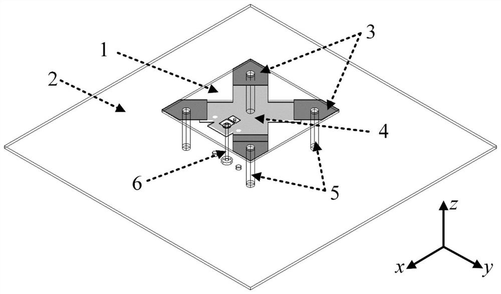
[0039]As an alternative embodiment, an ultra-small circularly polarized antenna based on an electromagnetic superresonator includes a dielectric substrate 1 and a metal floor 2, on which a plurality of stack capacitors, feeding devices and metal rings are formed. road connection end; the first electrodes of the stacked capacitors are electrically connected to each other to form the first common electrode of the stacked capacitor; the feeder is connected to the first common electrode of the stacked capacitor, and the metal loop connection end It is arranged on the second electrode of each laminated capacitor; the connecting ends of each metal loop are respectively electrically connected to one end of a metal post, and the other ends of each metal post are respective...


PUM

PropertyMeasurementUnit
diameteraaaaaaaaaa
lengthaaaaaaaaaa
thicknessaaaaaaaaaa

Abstract

The invention discloses an ultra-small circularly polarized antenna based on an electromagnetic superresonator, which includes a dielectric substrate and a metal floor, and a plurality of stacked capacitors, feeders and metal loop connection ends are formed on the dielectric substrate; The first electrodes of the stacked capacitors are electrically connected to each other to form a first common electrode of the stacked capacitors; The second electrode of the layer capacitor; the connecting ends of the metal loops are respectively electrically connected to one end of a metal post, and the other ends of the metal posts are respectively electrically connected to the metal floor; the electrically connected metal floor, metal post and Stack capacitors form the superresonator current loop. By adjusting the stacked capacitance and the length of the metal loop, a large equivalent capacitance and equivalent inductance are constructed to obtain a small resonance frequency and realize an ultra-miniature antenna design.

Description

technical field [0001] The invention belongs to the technical field of radio frequency antennas, relates to the technical field of small circularly polarized antennas, in particular to an ultra-small circularly polarized antenna based on an electromagnetic superresonator. Background technique [0002] With the advancement of miniaturization of electronic equipment, the problem of antenna size becomes more and more prominent, and there is an urgent need to develop miniaturized antennas with high performance. As an important branch of antennas, circularly polarized antennas are widely used in mobile communications, satellite communications, and electronic countermeasures. [0003] At present, the circularly polarized antennas commonly used in miniaturized electronic equipment can be roughly divided into orthogonal dipole pair circularly polarized antennas and microstrip circularly polarized antennas according to the antenna structure. Orthogonal dipole pair circularly polariz...

Claims


Application Information

Patent Timeline
Patent Type & Authority Patents(China)
IPC IPC(8): H01Q9/04H01Q1/38H01Q1/48H01Q1/50H01Q5/314
CPCH01Q1/38H01Q1/48H01Q1/50H01Q9/0428H01Q5/314
Inventor 董元旦王崭
Owner UNIV OF ELECTRONICS SCI & TECH OF CHINA
Why Eureka
Try Eureka