Gas-liquid separation assembly, alkali liquor regeneration tower and alkali liquor regeneration method

A technology of gas-liquid separation and regeneration tower, which is applied in separation methods, dispersed particle separation, chemical instruments and methods, etc. It can solve problems such as corrosion of sulfur dioxide in transportation pipelines, environmental problems that plague enterprises, and poor separation effects. It is easy to implement, Improve the efficiency of gas-liquid separation and the effect of simple installation

Active Publication Date: 2020-05-01
SINOPEC ENG +1
View PDF14 Cites 0 Cited by
  • Summary
  • Abstract
  • Description
  • Claims
  • Application Information

AI Technical Summary

Problems solved by technology

[0004] At present, there are two ways to separate tail gas and lye in the lye regeneration tower, one is to use a chimney baffle, and the other is to install a demister structure at the outlet of the tail gas for gas-liquid separation. The above two methods The separation effect is not good, and 100-200ppm of disulfides are often contained in the tail gas of the lye regeneration. When this part of disulfides is sent to the heating furnace or incinerator with the tail gas, it will cause corrosion of the pipeline and excessive sulfur dioxide generated by combustion. , has become an environmental issue that plagues the production of enterprises

Method used


Image

  • Gas-liquid separation assembly, alkali liquor regeneration tower and alkali liquor regeneration method
  • Gas-liquid separation assembly, alkali liquor regeneration tower and alkali liquor regeneration method
  • Gas-liquid separation assembly, alkali liquor regeneration tower and alkali liquor regeneration method

Examples


Embodiment

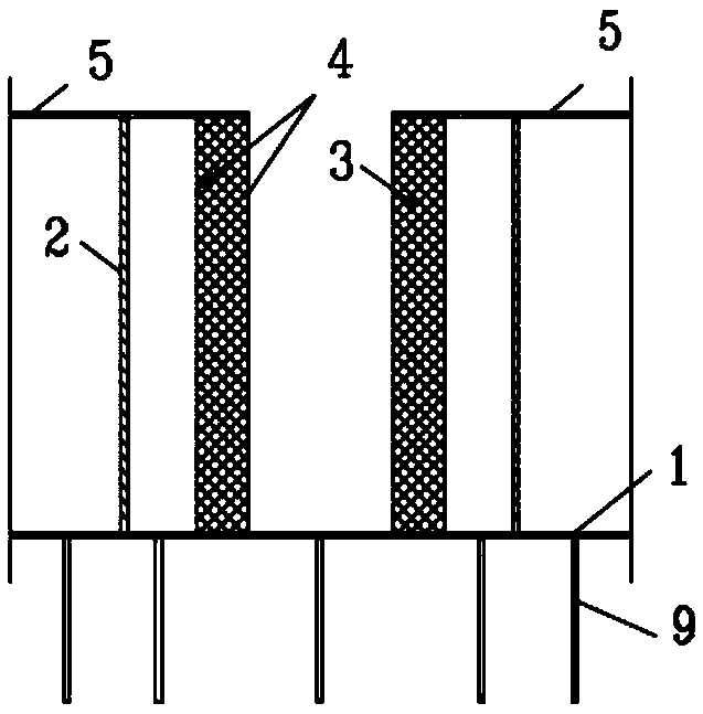
[0054] This embodiment adopts as Image 6 As shown in the lye regeneration tower, the tower body specification is the same as that of the comparative example, and the chimney baffle plate 17 is removed in the tower top space and installed Figure 1 to Figure 5 The gas-liquid separation assembly shown.

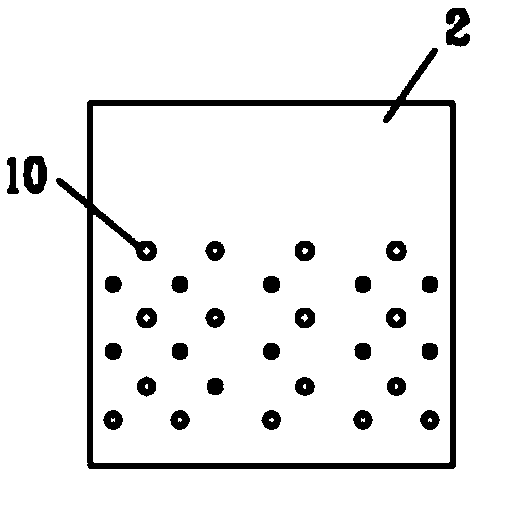
[0055]The device for reducing the sulfur content of alkali liquor regeneration tail gas comprises a base plate 1, a baffle plate 2, a wire mesh pad 3, a support structure 4 and a top plate 5; wherein, a plurality of first through holes are respectively distributed at both ends of the base plate 1, and the The edge is sealed with the inner wall of the alkali liquor regeneration tower, and two baffles are vertically fixed between the bottom plate 1 and the top plate 5 to form two gas inlet areas with the first through hole 7 in the middle of the bottom plate 1 and the top plate 5 and are located in the middle In the distribution area, the diameter of the first through hole 7 is ...


PUM

PropertyMeasurementUnit
Apertureaaaaaaaaaa
Diameteraaaaaaaaaa
Thicknessaaaaaaaaaa

Abstract

The invention relates to a gas-liquid separation assembly for an alkali liquor regeneration tower. The assembly comprises a bottom plate, a baffle plate, a silk screen separation piece and a top plate, the top plate and the bottom plate are arranged in parallel at intervals; the baffle plate is arranged between the top plate and the bottom plate, the top end and the bottom end of the baffle plateare fixedly connected with the top plate and the bottom plate correspondingly, so that the space between the bottom plate and the top plate is divided into a gas inlet area and a distribution area, first through holes are distributed in the bottom of the gas inlet area, so that the gas inlet area is in fluid communication with the space below the bottom plate through the first through holes; a second through hole is formed in the baffle plate, so that the gas inlet area is in fluid communication with the distribution area; the silk screen separation piece is arranged at an outlet of the distribution area, so that the distribution area is communicated with external fluid of the gas-liquid separation assembly through the silk screen separation piece; a liquid guide pipe is arranged on the lower surface of the bottom plate, the top end of the liquid guide pipe penetrates through the bottom plate, and the bottom end of the liquid guide pipe is a free end. The gas-liquid separation assemblycan improve the gas-liquid separation efficiency of alkali liquor regeneration tail gas and disulfide and reduce the content of disulfide in the tail gas.

Description

technical field [0001] The disclosure belongs to the field of deep processing of liquefied petroleum gas, and in particular relates to a gas-liquid separation component, an alkali liquor regeneration tower and an alkali liquor regeneration method. Background technique [0002] In the production and processing process of petrochemical enterprises, liquefied gas and gasoline fractions containing mercaptans and other sulfides produced by the main equipment such as atmospheric and vacuum, catalytic cracking, and coking cannot be directly used as products, and need to be refined to make them reach the product level. specification requirements. In the above-mentioned refining process, the lye extraction process is often used, and an lye regeneration system is provided. [0003] The key equipment of the lye regeneration system is the lye regeneration tower. Air is introduced into the lye regeneration tower. Under the action of the catalyst, the sodium mercaptide in the lye to be r...

Claims


Application Information

Patent Timeline
IPC IPC(8): B01D53/96B01D53/78B01D53/50
CPCB01D53/78B01D53/50B01D53/96
Inventor 张竹梅李依洋王宁
Owner SINOPEC ENG
Why Eureka
Try Eureka