Automatic welding device

An automatic welding and walking device technology, which is applied to welding equipment, welding accessories, arc welding equipment, etc., can solve the problems of continuous long production cycle of the production line, personal injury of operators, and error of steel belt alignment angle, etc., to improve production Efficiency and material utilization, eliminating potential safety hazards, and preventing the effect of feeding deviation

Inactive Publication Date: 2020-05-01
CHINA NAT BUILDING MATERIALS TECHCAL INNOVATION & RES INST LIMITED
View PDF21 Cites 3 Cited by
  • Summary
  • Abstract
  • Description
  • Claims
  • Application Information

AI Technical Summary

Problems solved by technology

[0003] At present, in the process of steel strip processing and production, after the production of the front steel strip, it is necessary to manually put the head of the steel strip at the back into the forming machine. During this process, the operation of the production line must be suspended, so that the production line cannot continue for a long production cycle.
Moreover, the alignment time of the manual alignment feeding method is uncontrollable, and there may be errors in the alignment angle of the steel strips fed into the forming machine, resulting in the produced products becoming waste products and reducing the yield
There may be potential safety hazards in the process of straightening the steel belt, which may cause personal injury to the operator

Method used


Image

  • Automatic welding device
  • Automatic welding device

Examples


Embodiment Construction

[0027] In order to make the purpose, technical solutions and advantages of the embodiments of the present invention clearer, the technical solutions in the embodiments of the present invention will be clearly and completely described below in conjunction with the drawings in the embodiments of the present invention. Obviously, the described embodiments It is a part of embodiments of the present invention, but not all embodiments. Based on the embodiments of the present invention, all other embodiments obtained by persons of ordinary skill in the art without making creative efforts belong to the protection scope of the present invention. It should be noted that, in the case of no conflict, the embodiments in the present application and the feature vectors in the embodiments can be combined arbitrarily with each other.

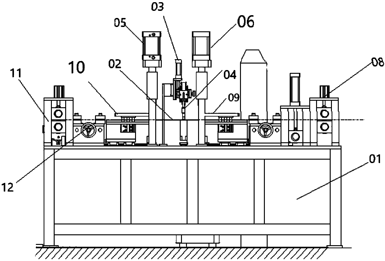
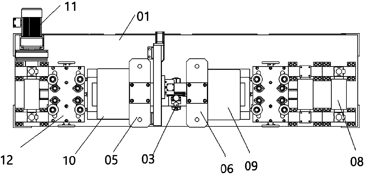
[0028] like figure 1 , 2 As shown, an automatic welding device, a machine tool base 01, a welding operation table 02 arranged on the machine tool base 01, a w...


PUM


Abstract

The invention discloses an automatic welding device which comprises a machine tool base (01), a welding operation table (02), a welding gun walking device (03), a welding gun (04), a first shear mechanism (05), a second shear mechanism (06) and a control system. The machine tool base (01) is divided into a feeding area located on one side of the welding operation table (02) and a pushing area located on the other side of the welding operation table (02). A locating and welding clamp groove communicating with the feeding area and the pushing area is arranged on the welding operation table (02).A pressing rolling shaft (08) away from the welding operation table (02), a pressing pushing mechanism (09) close to the welding operation table (02) and a material tail detection switch in inductionconnection with the pressing rolling shaft (08) and the pressing pushing mechanism (09) are arranged in the pushing area of the machine tool base (01). A conveying rolling shaft (11) and a material head detection switch in induction connection with the conveying rolling shaft (11) are arranged in the feeding area of the machine tool base (01).

Description

technical field [0001] The invention relates to the technical field of steel strip production, in particular to a steel strip welding device. Background technique [0002] In the past 20 years, with the development of digitization, automation, computer and mechanical design technology, as well as the high emphasis on welding quality, automatic welding has developed into an advanced manufacturing technology, and automatic welding equipment has played an important role in the application of various industries. The role is getting bigger and bigger, and the scope of application is expanding rapidly. In modern industrial production, the mechanization and automation of the welding production process is an inevitable trend in the modernization of the welding mechanism manufacturing industry. [0003] At present, in the steel strip processing and production process, after the front steel strip is produced, it is necessary to manually align the material head of the rear steel strip...

Claims


Application Information

Patent Timeline
Patent Type & Authority Applications(China)
IPC IPC(8): B23K9/16B23K9/32B23P23/04B23P23/06
CPCB23K9/16B23K9/32B23P23/04B23P23/06
Inventor 许刚谢富冬
Owner CHINA NAT BUILDING MATERIALS TECHCAL INNOVATION & RES INST LIMITED
Why Eureka
Try Eureka