Impressing device for preparing crystalline silicon solar cell electrode

A solar cell and electrode technology, which is applied in printing, circuit, printing machine, etc., can solve the problem of not being able to eliminate the peak and valley fluctuations at the top of the longitudinal section of the line, not being able to overcome the inherent defects of screen printing, and the elasticity of the steel plate is not as good as the screen screen, etc. problem, to achieve good long-term continuity, uniform electrode grid lines, and low cost

Pending Publication Date: 2020-05-05
TIANJIN AIKO SOLAR ENERGY TECH CO LTD
View PDF0 Cites 1 Cited by
  • Summary
  • Abstract
  • Description
  • Claims
  • Application Information

AI Technical Summary

Problems solved by technology

[0005] (1) The mesh knot or steel wire at the opening of the screen will form ups and downs on the electrode grid, and the grid line resistance will be higher at the trough of the line. The current advanced screen no-network technology is only by reducing the opening. The proportion of the steel wire increases the opening ratio to reduce the fluctuation of the grid electrode, but it cannot eliminate the peak-valley fluctuation at the top of the longitudinal section of the wire
[0006] ⑵Because the screen is in the process of printing from the lower knife position to the knife receiving position, from the edge of the scraper to the middle position, the force on the whole screen plate is not uniform, so the shape of the formed lines is not uniform. For shading and The influence of resistance is also different, and the unevenness of the electrode grid will cause the loss of light and electricity
[0007] (3) After the paste is repeatedly printed on the screen, the proportion of small molecular resin components that are easy to pass through the screen in the paste gradually decreases, while the proportion of long-chain molecular resin components that are not easy to pass through the screen continues to increase. At the same time, the solvent continues to volatilize. The screen penetration of the slurry is getting worse and worse, and the number of broken grids and virtual printing is gradually increasing, resulting in a decline in battery performance
[0008] (4) The tension and other properties of the screen plate will rapidly decay with the increase of the number of uses, resulting in the worsening of the prepared grid electrode, and the performance of the battery will also decrease with the increase of the number of uses of the screen plate.
[0009] Although there are attempts to replace screen printing with stencil printing to solve the problem of the influence of grid knots on grid electrodes, the elasticity of steel plates is not as good as that of screen printing, and stencil printing cannot overcome the inherent defects of screen printing. , so stencil printing is still in the concept stage and has not been put into use

Method used


Image

  • Impressing device for preparing crystalline silicon solar cell electrode

Examples


Embodiment 1

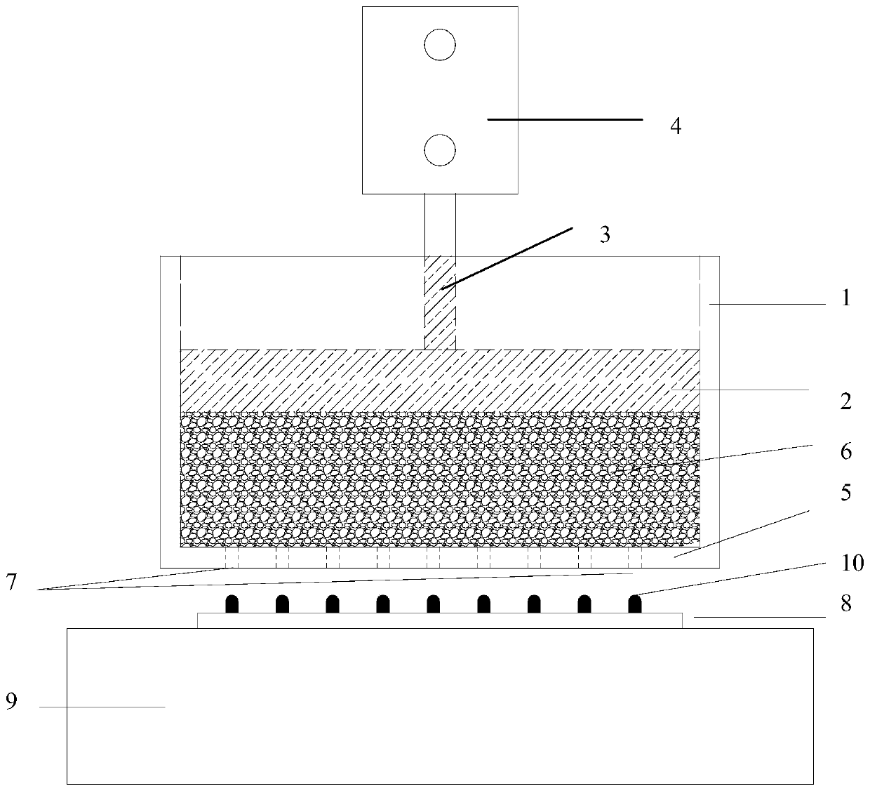
[0026] Such as figure 1 As shown, it is an imprinting device for preparing crystalline silicon solar cell electrodes according to the present invention, which includes a groove-shaped casing 1, a piston 2 built in the casing 1, a connecting rod 3 and a driving mechanism, and the casing can adopt Metal material, alloy material, glass material, organic resin material, ceramic material or carbon fiber material. In this embodiment, the driving mechanism adopts the air cylinder 4 , and in other embodiments, the driving mechanism may adopt an oil pressure cylinder, a screw slide rail electrode or a linear electrode. The bottom surface of the housing 1 is a flat plate and the flat plate is a hollow plate 5 with a hollow grid electrode pattern. The hollow part 7 on the hollow plate 5 is mainly composed of several hollow long holes arranged in parallel. The hollow long holes are a complete through hole. The periphery of the piston 2 is in contact with the inner wall of the housing 1 ...

Embodiment 2

[0030] The difference between this embodiment and Embodiment 1 lies in that: the hollowed out part on the hollowed out plate is different, and the electrode prepared in this embodiment is a rear grid line electrode. In this embodiment, the hollow part on the hollow plate is mainly composed of several hollow long holes arranged in parallel, and the hollow long holes are divided into a plurality of hole segments, and the shape of each hole segment is a triangle. In other embodiments, The shape of the hole segment can also be circular, rectangular or elliptical, etc.

[0031] The working process of this embodiment is as follows: when in use, the cylinder pushes the connecting rod to reciprocate up and down, the connecting rod pushes the piston to move up and down, the piston squeezes the slurry when it moves down, and the slurry passes through the hollow of the hollow plate under the action of the extrusion force. Parts (specifically, each hole segment) are printed on the surface...


PUM


Abstract

The invention discloses an impressing device for preparing a crystalline silicon solar cell electrode. The impressing device comprises a shell, a piston and a driving mechanism, wherein the bottom surface of the shell is a flat plate which is a hollow plate with a hollow grid electrode pattern, the circumference of the piston makes contact with the inner wall of the shell so as to form a closed space for containing slurry between the piston and the hollow plate, the piston can be driven to reciprocate up and down by the driving mechanism, and the slurry is extruded when the piston moves downwards, so that the slurry leaks on a silicon wafer through the hollow part of the hollow plate, and the electrode which corresponds to the shape of the hollow part is formed. Electrode grid lines prepared by the impressing device are uniform and consistent, the fluctuating condition of peaks and valleys cannot occur, the depth-width ratio of the electrode is high, the slurry leaks through extrusionin the lower closed space, solvents in the slurry are difficult to volatilize, and different proportions of components can be kept consistent for a long time; the electrode grid lines prepared by theimpressing device has good long-time continuity, so that the quality of the electrode is increased, the cell performance is improved, and the manufacturing cost is reduced.

Description

technical field [0001] The invention belongs to the preparation technology of crystalline silicon solar battery electrodes, in particular to an imprinting device for preparing crystalline silicon solar battery electrodes. Background technique [0002] Photovoltaic energy, as one of the clean energy sources, has achieved tremendous development all over the world. As the main force of photovoltaic energy, crystalline silicon cells have played a pivotal role in the development of photovoltaic energy. At the same time, crystalline silicon solar cells themselves are also It has made great progress, and various new technologies have emerged and been applied, which has continuously promoted the efficiency and cost reduction of photovoltaic power generation. The photovoltaic electricity price has gradually approached the grid parity electricity price. [0003] Regardless of the battery structure, the metal electrode is the most important part of the indispensable electric current. T...

Claims


Application Information

Patent Timeline
Patent Type & Authority Applications(China)
IPC IPC(8): B41F15/08B41F15/14H01L31/0224
CPCB41F15/08B41F15/14H01L31/022433Y02E10/50
Inventor 顾生刚夏利鹏刘海金郭星妙杨二存
Owner TIANJIN AIKO SOLAR ENERGY TECH CO LTD
Why Eureka
Try Eureka