Automatic inflow control device and pipe column

A technology of inflow control and control devices, which is applied in the direction of mining fluid, wellbore/well components, earthwork drilling and production, etc., can solve the problems of complex flow channels, abrasion, valve body channel blockage, etc., and achieve good chemical stability and flow channel Simple structure and long service life

Active Publication Date: 2020-05-05
CHINA NAT OFFSHORE OIL CORP +2
View PDF16 Cites 3 Cited by
  • Summary
  • Abstract
  • Description
  • Claims
  • Application Information

AI Technical Summary

Problems solved by technology

Conventional passive inflow control tools currently used have limited effect on delaying water flooding. The main problems are: inability to distinguish the nature of the inflow fluid (crude oil, water, crude oil with water), and general restrictions on oil or water, resulting in certain oil production In particular, it also plays a role in controlling the crude oil with a very low water content; the excess flow of the device cannot be automatically adjusted according to the water content after the bottom water is put in
At present, there are some automatic inflow control tools with intelligent selection and suppression functions for fluids. The more mature ones include floating disc type and flow channel control type, etc., but the complexity of the flow channel will cause sand particles to form sand accumulation in the flow channel. And the disadvantage of gradually clogging the flow channel
[0003] In the actual oilfield production process, the water cut rises too fast and water control is required, and the following other problems often occur, which lead to production interruption, affect production efficiency, increase workover costs, and may even lead to early scrapping of production wells: Some wells need sand control, and some wells have high fine silt content, so there is a risk of blockage of the valve body channel and risk of tool erosion by sandy fluid; in order to meet the production demand, there is a need to increase the pressure difference to increase production; due to the difference in oil properties , easy to scale and wax in the wellbore

Method used


Image

  • Automatic inflow control device and pipe column
  • Automatic inflow control device and pipe column
  • Automatic inflow control device and pipe column

Examples


Embodiment approach

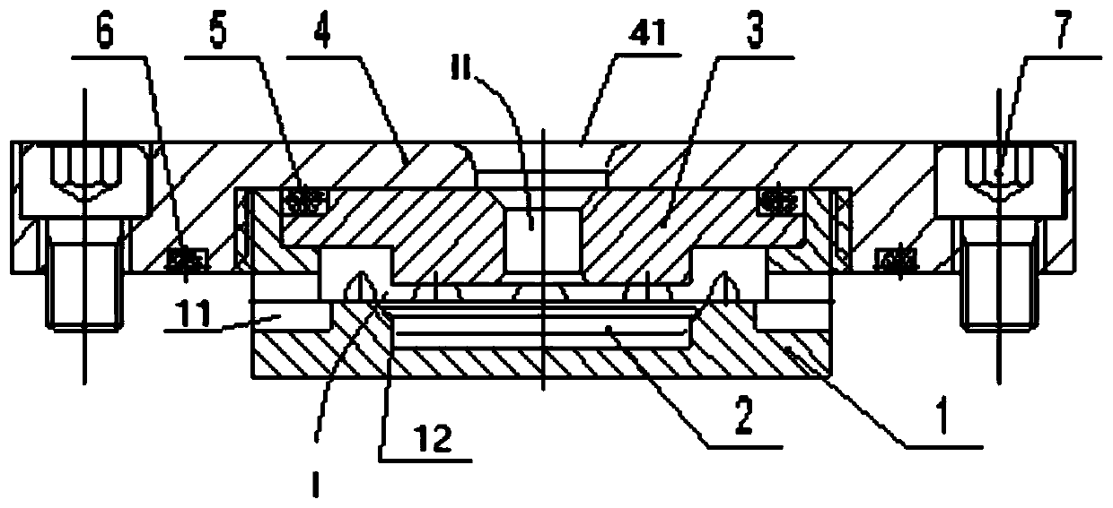
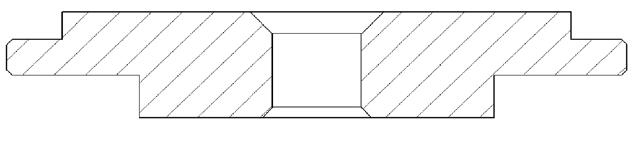
[0039] According to one embodiment of the present invention, the inner bottom surface of the lower housing 1 is provided with a groove 12, and the upper edge of the groove 12 is a tapered mouth, and the diameter of the mouth becomes larger along the direction of the taper. The outer peripheral surface of the lower end of the disc 2 is adapted to the inner peripheral surface of the groove 12, and the outer edge of the upper edge of the disc 2 is a tapered flange, and the outer tapered surface of the flange is compatible with the inner peripheral surface of the groove. The upper edge matches the inner side, and the depth of the groove 12 is greater than the height of the lower end of the disc 2 . This technical solution further increases the pressurization chamber III between the disc 2 and the lower case 1, that is, the cavity between the bottom of the disc 2 and the bottom of the lower case, as image 3 As shown, thus allowing the AICD (Automatic Inflow Control Device) to withs...

Embodiment

[0076] As shown in Figures 1 to 3, the automatic inflow control device of this embodiment consists of a lower casing 1, a disc disc 2, a middle cover 3, an upper casing 4, a sealing ring 5, a sealing ring 6, a screw 7, and an opening. Base pipe 8 is composed. When assembling, the disc disc 2 is installed in the middle of the lower housing 1, and then the middle cover 3 and the sealing ring 5 are loaded into the upper housing 4, and the connection between the lower housing 1 and the upper housing 4 is completed. It can be a threaded connection or other lockable mechanical connection, and the sealing ring 6 and the screw 7 are installed after the assembly is completed. The automatic inflow control unit is assembled.

[0077] Install the assembled automatic inflow control device on the perforated base pipe 8, and process it into an automatic inflow control nipple, so that the fluid can only flow from the upper casing 4 through the middle cover 3, into the flow control chamber, a...


PUM


Abstract

The invention relates to an automatic inflow control device and a pipe column. The automatic inflow control device comprises an upper shell, a lower shell and a disc. A fluid inlet is formed in the upper shell. A cavity is formed between the upper shell and the lower shell, a fluid channel is formed between the fluid inlet and the cavity, and the disc is suitable for flowing in the cavity. Fluid outlets are formed in the side face of the cavity. The pipe column comprises sealing separation media and the automatic inflow control devices. The multiple automatic inflow control devices which are connected through a porous base pipe are arranged in the pipe column, and the corresponding sealing separation media are arranged between every two adjacent automatic inflow control devices. The automatic inflow control device and the pipe column have the advantages of blockage resistance, high pressure difference resistance and scale formation resistance, and are particularly suitable for exploitation of an oilfield which is characterized in that the nonhomogeneity is high, bottom water coning operation is fast, and the water content is high.

Description

technical field [0001] The invention relates to the technical field of petroleum engineering, in particular to an automatic inflow control device and a pipe string. Background technique [0002] Bottom water coning and premature water flooding of production wells are one of the most common problems in oil production. Conventional passive inflow control tools currently used have limited effect on delaying water flooding. The main problems are: inability to distinguish the nature of the inflow fluid (crude oil, water, crude oil with water), and general restrictions on oil or water, resulting in certain oil production In particular, it also plays a role in controlling the crude oil with a very low water content; after the bottom water is put in, the excess flow of the device cannot be automatically adjusted according to the water content. At present, there are some automatic inflow control tools with intelligent selection and suppression functions for fluids. The more mature o...

Claims


Application Information

Patent Timeline
Patent Type & Authority Applications(China)
IPC IPC(8): E21B43/12E21B43/32
CPCE21B43/12E21B43/32
Inventor 刘书杰潘豪易会安曹砚锋李汉兴王彬梁丹
Owner CHINA NAT OFFSHORE OIL CORP
Why Eureka
Try Eureka