
Coal-fired power generation unit single-tank molten salt thermocline heat storage system and method

A technology of generator set and heat storage system, which is applied in the steam generation method using heat carrier, heat storage equipment, type of heat exchanger, etc., can solve the problem that affects the continuous and stable operation of the steam turbine power generation system, and it is difficult to guarantee the heat on the user side in real time. , The safety requirements of generator sets are getting higher and higher, so as to achieve the effect of realizing rapid response, improving flexibility and peak regulation ability, and improving the ability of long-term stable operation.

Pending Publication Date: 2020-05-05
CHINA HUANENG GRP CO LTD +1
View PDF2 Cites 6 Cited by
  • Summary
  • Abstract
  • Description
  • Claims
  • Application Information

AI Technical Summary

Problems solved by technology

The violent fluctuation of the load has brought huge potential safety hazards, affecting the continuous and stable operation of the steam turbine power generation system, and the safety requirements for the generator set are getting higher and higher
[0007] However, the operation mode and control mode of traditional thermal power generating units are difficult to achieve rapid response to load, to solve the problem of stable operation of the unit, and to ensure the demand for heat on the user side in real time. In order to improve the flexibility of unit operation and peak shaving capacity, effectively reduce system costs, and meet the heat demand of the user side in real time, using a single-tank molten salt thermocline heat storage system and method

Method used


Image

  • Coal-fired power generation unit single-tank molten salt thermocline heat storage system and method

Examples


Embodiment Construction

[0034] Below in conjunction with accompanying drawing, the present invention is described in further detail:

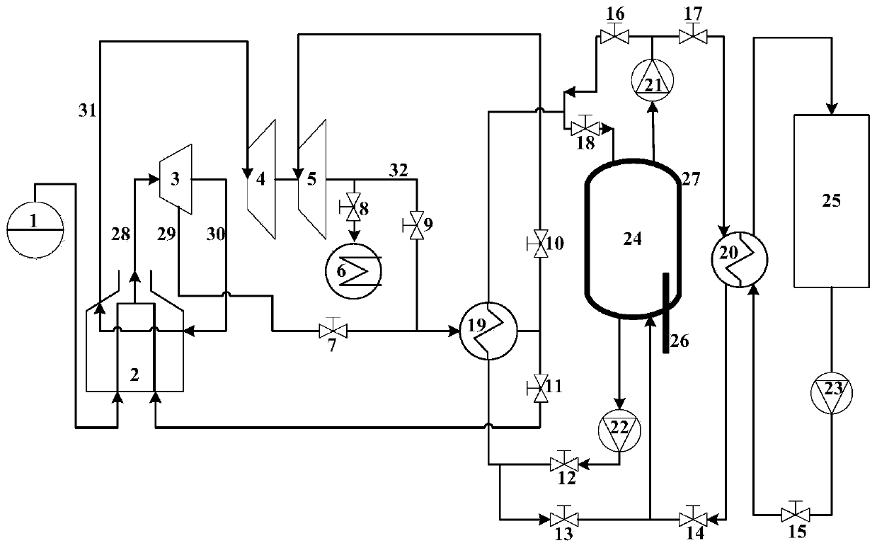
[0035] refer to figure 1 , a single-tank molten salt thermocline layer heat storage system for a coal-fired generator set according to the present invention, comprising steam entering a boiler 2 through a steam drum 1 for heating and then entering a high-pressure cylinder 3 of a steam turbine, connecting the steam extraction port of the high-pressure cylinder 3 of the steam turbine to the The first heat exchanger 19 communicates with the steam extraction pipe 29 of the high-pressure cylinder, and the reheat steam pipe 31 communicates the reheat steam of the boiler 2 with the medium-pressure cylinder 4 of the steam turbine. device 6; the steam inlet of the low-pressure cylinder 5 of the steam turbine is also connected with the high-temperature steam outlet of the first heat exchanger 19, and the exhaust port of the low-pressure cylinder 5 of the steam turbine is connec...


PUM


Abstract

The invention discloses a coal-fired power generation unit single-tank molten salt thermocline heat storage system and method. The system comprises a molten salt thermocline heat storage tank, a firstheat exchanger and a second heat exchanger, wherein a molten salt outlet in the top of the molten salt thermocline heat storage tank communicates with the first heat exchanger and the second heat exchanger, a bottom outlet of the molten salt thermocline heat storage tank communicates with the first heat exchanger, an outlet of the first heat exchanger communicates with an inlet of the molten saltthermocline heat storage tank, a steam inlet of the first heat exchanger communicates with a turbine high-pressure cylinder and a turbine low-pressure cylinder, a steam outlet of the first heat exchanger communicates with a steam inlet of the turbine low-pressure cylinder and an inlet of a boiler, a molten salt outlet of the second heat exchanger communicates with a molten salt inlet in the bottom of the molten salt thermocline heat storage tank, and the second heat exchanger communicates with a heat supply system. The system is helpful for realizing quick response to the load change of a power grid, can effectively improve the flexibility and peak regulation capability of operation of a unit, and is helpful for improving the long-term stable operation capability of the unit.

Description

technical field [0001] The invention belongs to the technical field of thermal power generation and energy storage, and in particular relates to a single-tank molten salt thermocline layer heat storage system and method for a coal-fired power generation unit. Background technique [0002] Molten salt belongs to a heat storage material integrating "endothermic-heat storage". It refers to salt in a molten state, including inorganic salts, oxide melts, and molten organic substances. The molten salts generally referred to are inorganic salts, of which the two most commonly used types of salts are nitrates and carbonates. Molten salt has the advantages of low cost and stable chemical properties. It can maintain a liquid state without phase change during the heat absorption process, has the characteristics of large heat capacity and high heat transfer coefficient. [0003] Single-tank thermocline heat storage uses a heat storage tank, usually using molten salt or heat transfer oi...

Claims


Application Information

Patent Timeline
Patent Type & Authority Applications(China)
IPC IPC(8): F22B1/06F28D20/00
CPCF22B1/06F28D20/0034F28D2020/0047Y02E60/14
Inventor 赵东明赵志国秦校军刘明义姚帅周宇
Owner CHINA HUANENG GRP CO LTD
Learn More