
Field effect sensor and detection method and detection system thereof

A field effect and sensor technology, applied in the field of sensors, can solve the problems of reducing sensor precision, increasing sensor cost, reducing sensor sensitivity, etc., and achieve the effects of reducing noise, improving precision, and improving sensitivity

Active Publication Date: 2020-05-05
ZHEJIANG UNIV
View PDF8 Cites 0 Cited by
  • Summary
  • Abstract
  • Description
  • Claims
  • Application Information

AI Technical Summary

Problems solved by technology

[0004] However, in the actual use of field effect semiconductor devices, packaging technology is required to improve the reliability of the device. However, the packaging process will introduce a certain series resistance to the device, especially in liquid sensors, the series resistance cannot be ignored.
In the traditional detection method, the series resistance introduced in the packaging process will greatly reduce the sensitivity of the sensor and introduce noise, thereby reducing the accuracy of the sensor (accuracy = (3*noise root mean square) / sensitivity), for this problem, the current The solution can only be through complex technical means such as differential sensing circuit and negative feedback signal processing, without optimizing and improving the design and detection method of the sensor itself. The traditional solution increases the complexity of the sensor and greatly improves the performance of the sensor. The cost of the sensor reduces the reliability of the sensor, and requires complex detection equipment to work with the sensor

Method used


Image

  • Field effect sensor and detection method and detection system thereof
  • Field effect sensor and detection method and detection system thereof
  • Field effect sensor and detection method and detection system thereof

Examples


Embodiment Construction

[0020] Specific embodiments of the present invention will be described in detail below in conjunction with the accompanying drawings. It should be noted that the embodiments described here are only for illustration and are not intended to limit the present invention. In the following description, numerous specific details are set forth in order to provide a thorough understanding of the present invention. However, it will be understood by one of ordinary skill in the art that these specific details are not required to practice the present invention. Furthermore, in some embodiments, well-known circuits, materials or methods have not been described in detail in order to avoid obscuring the present invention.

[0021] Throughout this specification, reference to "one embodiment," "an embodiment," "an example," or "example" means that a particular feature, structure, or characteristic described in connection with the embodiment or example is included in the present invention. In ...


PUM


Abstract

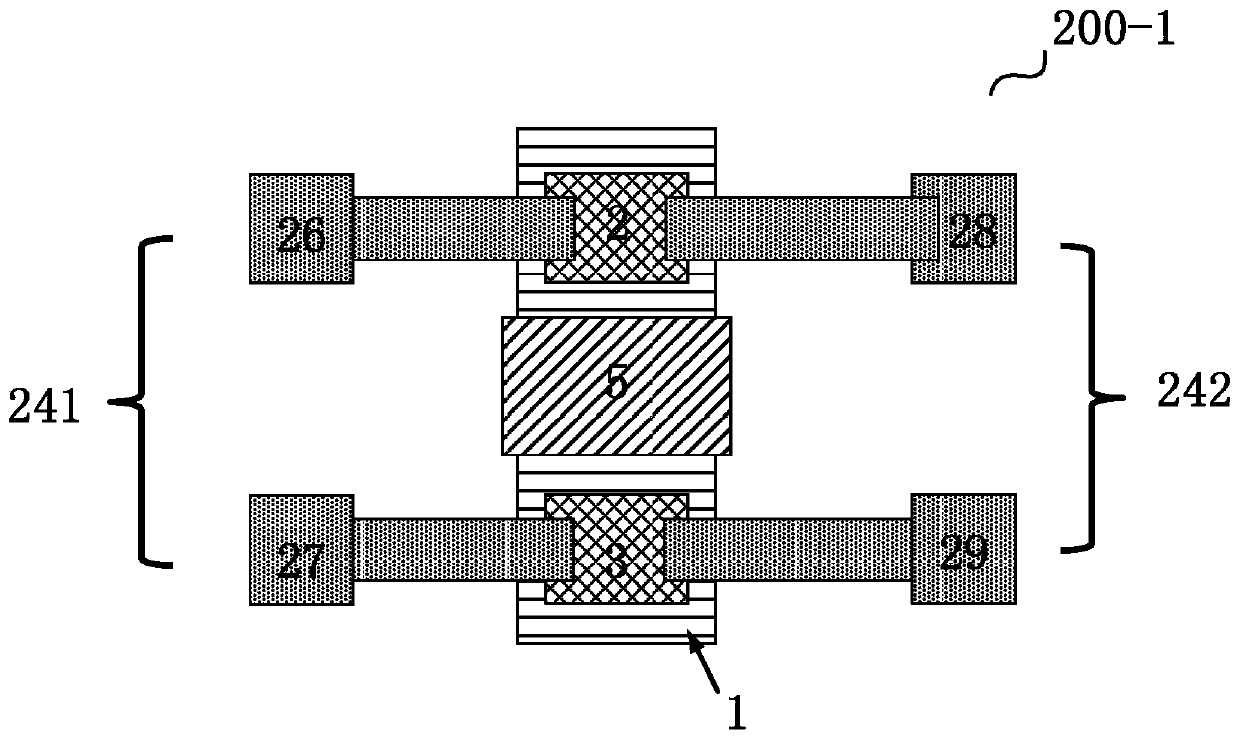
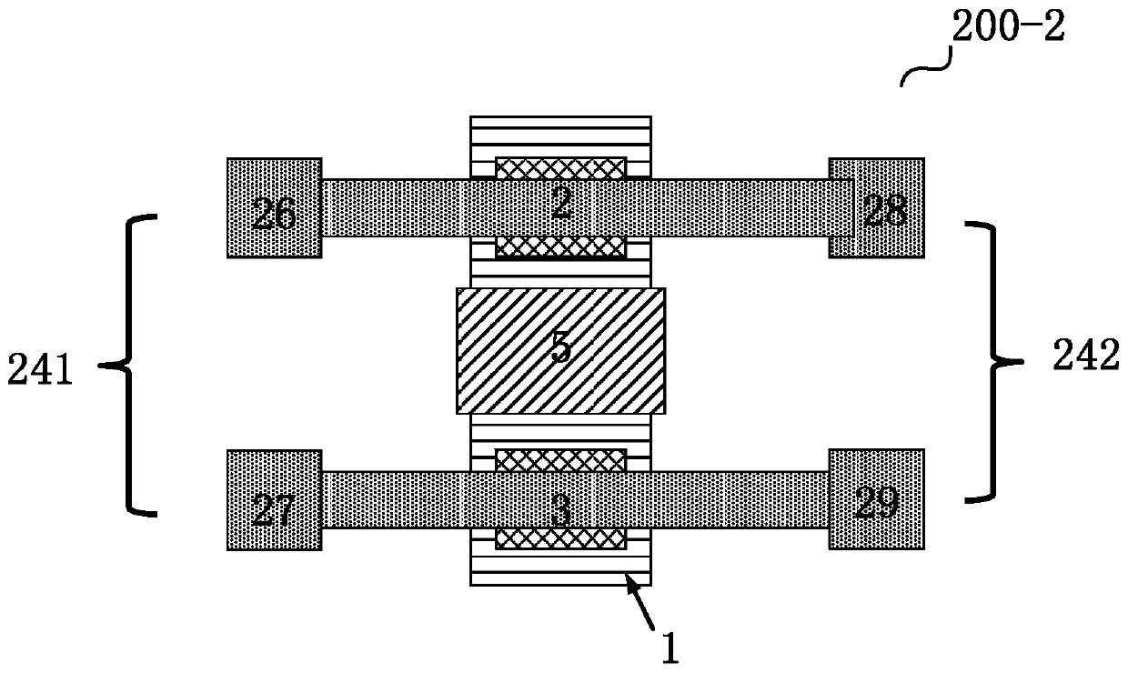
The invention discloses a field effect sensor and a detection method and a detection system thereof. The field effect sensor comprises a field effect semiconductor device and a sensitive film. The field effect semiconductor device is provided with a grid electrode, a source electrode, a drain electrode and a channel. The sensitive film is in contact with a grid electrode of the field effect semiconductor device and is used for being in specific contact with a detected substance to generate potential change. The detection method comprises: applying a constant voltage to a first pair of electrodes, and the first pair of electrodes being connected with a source electrode and a drain electrode respectively; simultaneously detecting current on the first pair of electrodes and voltage on a second pair of electrodes, wherein the second pair of electrodes are respectively connected with the source electrode and the drain electrode; and obtaining a detection signal of the detected substance according to the voltage on the second electrodes and the current on the first electrodes. According to the detection method of the field effect sensor, two pairs of electrodes are utilized, the influence brought by series resistance introduced in the packaging process is avoided, the sensitivity of the sensor is improved, and noise is reduced.

Description

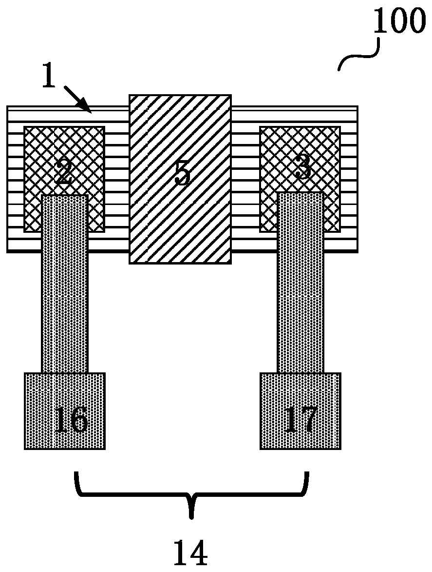
technical field [0001] The present invention relates to a sensor, in particular to a field effect sensor and its detection method and detection system. Background technique [0002] Field-effect semiconductor device sensors, such as silicon-based ISFET (ion-selective field-effect sensor), gallium nitride (GaN)-based HEMT (high electron mobility device) devices, etc., are in contact with the sensitive film through the material to be sensed. The potential of the sensitive film is changed, and the sensitive film is connected to the gate of the field effect semiconductor sensor device, thereby changing the gate potential, and then modulating the Fermi level of the device channel, and changing the channel resistance to realize the sensing function. [0003] Conventional field effect sensors 100 such as figure 1 As shown, it includes a field effect semiconductor device and a sensitive film 5. The sensitive film 5 is positioned on the gate surface of the field effect semiconductor...

Claims


Application Information

Patent Timeline
IPC IPC(8): G01N27/414
CPCG01N27/4148
Inventor 张瀚元杨树盛况
Owner ZHEJIANG UNIV
Learn More