Automatic bone drilling device

An automatic drill and drill clamp technology, applied in the field of medical equipment, can solve the problems of limited load, large mass, and long-term stability of the mechanical arm, and achieve the effect of weight reduction and easy operation

Active Publication Date: 2020-05-08
NANJING TUODAO MEDICAL TECHNOLOGY CO LTD
View PDF3 Cites 3 Cited by
  • Summary
  • Abstract
  • Description
  • Claims
  • Application Information

AI Technical Summary

Problems solved by technology

Although this automatic bone drilling device greatly saves the operation time, not only is the stability not high due to the too long operating part of the Kirschner wire, but also the clamping method is easy to be unstable. It is a disposable instrument, and the bolt disassembly is too c

Method used


Image

  • Automatic bone drilling device
  • Automatic bone drilling device
  • Automatic bone drilling device

Examples


Embodiment Construction

[0044] The present invention will be further explained below in conjunction with the accompanying drawings and specific embodiments.

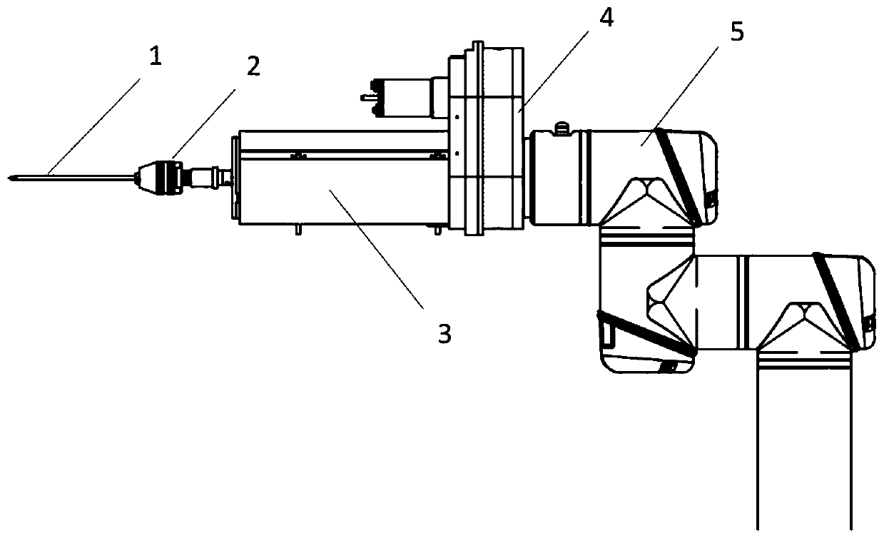
[0045] figure 1 It is the structural diagram of the automatic bone drilling device, such as figure 1 As shown, the automatic bone drilling device of the present invention includes a Kirschner wire 1, a rotating mechanism 2 and a feeding mechanism 3, the feeding mechanism 3 is fixedly connected with the mechanical arm 5 through a transition piece 4, and the rotating mechanism 2 is connected by screws (not limited to this Connection) On the outer cylinder 3-15 of the feed mechanism 3, the Kirschner wire 1 is fixed on the drill clip 2-9 of the rotary mechanism 2.

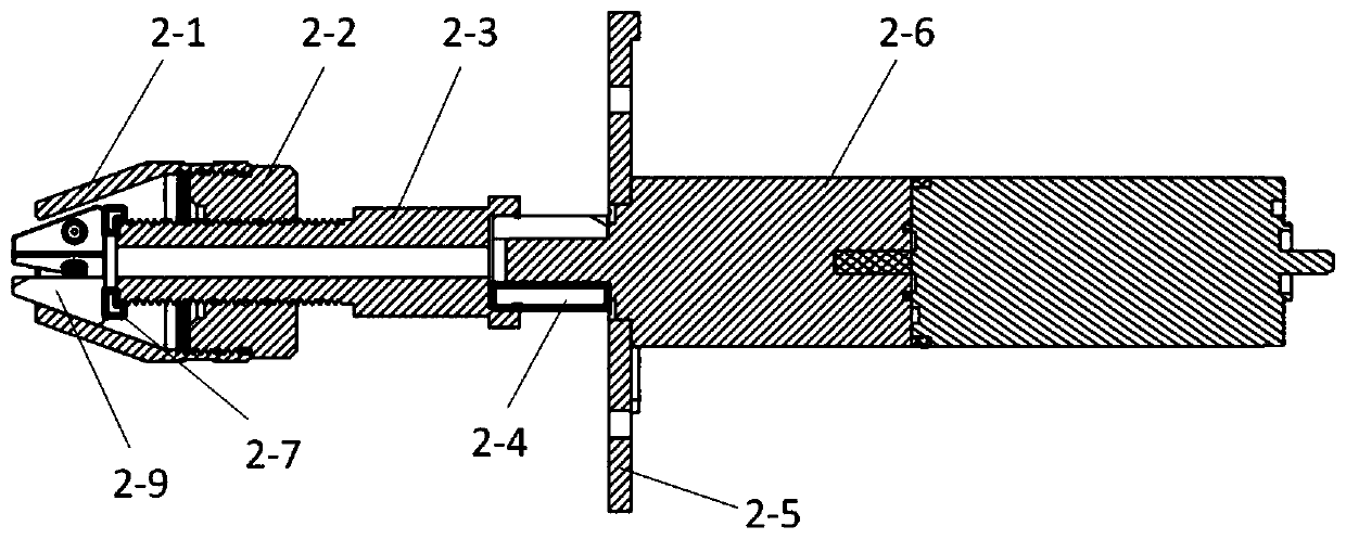
[0046] figure 2 is a sectional view of the rotation mechanism of the automatic bone drilling device, such as figure 2 As shown, the rotating mechanism 2 includes a rotating motor 2-6, a connecting piece 2-4, a threaded push rod 2-3, an intermediate threaded rod 2-2, a fixed sleeve 2-...


PUM


Abstract

The invention discloses an automatic bone drilling device. The device comprises a feeding mechanism (3), a rotating mechanism (2) installed on the feeding mechanism (3), and a Kirschner wire (1) installed on the rotating mechanism (2); and the rotating mechanism (2) has a hollow structure, the Kirschner wire (1) is fixed after being inserted into the rotating mechanism (2), and the insertion depthof the Kirschner wire (1) is adjustable. According to the device, the rotating mechanism is set as the hollow structure, so that the exposed length of the operation part of the Kirschner wire can beadjusted, and the device is simple and convenient to operate without being assembled and disassembled by bolts; and in addition, the feeding mechanism and the rotating mechanism of the device are improved in structure, the volume and mass are greatly reduced, and the device can realize fully automatic operation of spinal bone drilling.

Description

technical field [0001] The invention relates to the field of medical instruments, in particular to an automatic bone drilling device. Background technique [0002] Vertebral body enhancement is a technique that injects bone cement or artificial bone into the diseased vertebral body through percutaneous puncture under the guidance of medical imaging images to strengthen the vertebral body. Most of the existing spine drilling devices are manual, and the manual puncture device includes a puncture needle, a working channel, a guide pin and a hand drill, wherein the puncture needle includes a needle tube and a needle inserted in the needle tube. During the puncture process, the doctor needs to cut an incision on the patient's skin first; then insert the puncture needle into the lesion of the patient, then take out the needle and keep the needle tube; then insert the guide needle into the needle tube of the puncture needle, keep the guide needle and take out the needle tube of the...

Claims


Application Information

Patent Timeline
IPC IPC(8): A61B17/16
CPCA61B17/162A61B17/1626A61B17/1628A61B17/1633A61B17/1671
Inventor 程敏赵亚平王锋梁海鹏
Owner NANJING TUODAO MEDICAL TECHNOLOGY CO LTD
Why Eureka
Try Eureka