Lathe chuck
A technology of a lathe chuck and a chuck body, which is applied in the field of machine tools, can solve the problems of unfavorable machine tool processing automation, high labor intensity of operators, large clamping stroke, etc., and achieves convenient automatic clamping, large clamping stroke, and improved production. The effect of efficiency
- Summary
- Abstract
- Description
- Claims
- Application Information
AI Technical Summary
Problems solved by technology
Method used
Image
Examples
Embodiment 1
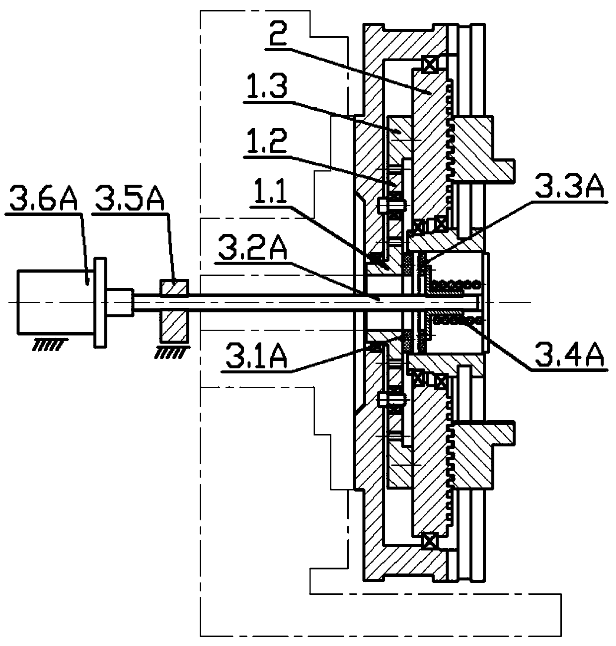
[0035] Such as figure 1 A horizontal lathe chuck shown is coaxially provided with a planetary reduction mechanism 1 in the chuck body, the output end of the planetary reduction mechanism 1 is connected to the spiral groove disk 2 in the chuck body, and the input end is movably connected with resistance Torque input mechanism. In order to increase the output torque at the output end of the planetary reduction mechanism 1, the output end of the planetary reduction mechanism 1 is a low-speed end, and the input end of the planetary reduction mechanism 1 is a high-speed end. The planetary reducer has three deceleration and boosting methods. In this embodiment, the resistance torque input mechanism is connected with the sun gear 1.1 of the planetary reduction mechanism 1, the spiral groove disc 2 is connected with the inner ring gear 1.3 of the planetary reduction mechanism 1, and the planetary The frame 1.2 is fixedly connected with the chuck body. The resistance torque input mec...
Embodiment 2
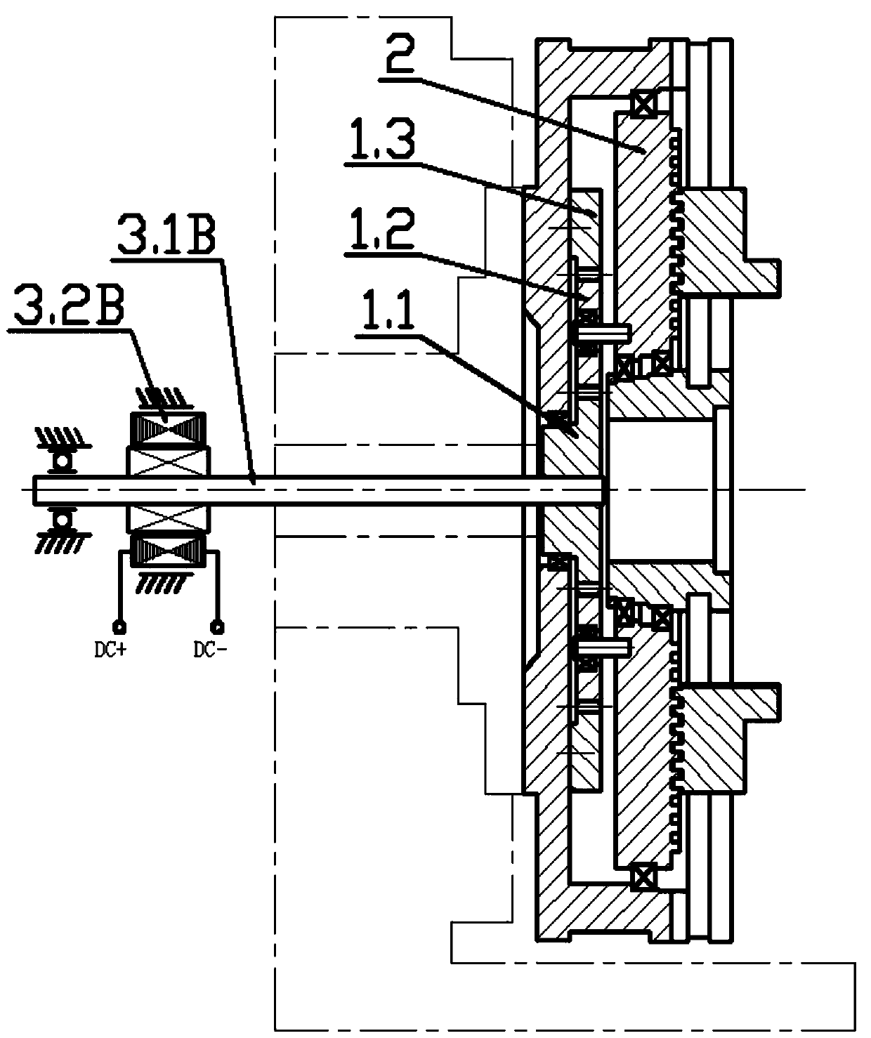
[0039] Such as figure 2 In the shown horizontal lathe chuck, a planetary reduction mechanism 1 is coaxially arranged in the chuck body. The output end of the planetary reduction mechanism 1 is a low-speed end, and the input end of the planetary reduction mechanism 1 is a high-speed end. The low-speed end of the planetary reduction mechanism 1 is connected to the spiral groove disc 2 in the chuck body, and the high-speed end is movably connected with a resistance torque input mechanism. Specifically, the resistance torque input mechanism is connected to the sun gear 1.1 of the planetary reduction mechanism 1, the spiral groove disc 2 is connected to the planet carrier 1.2 of the planetary reduction mechanism 1, and the ring gear 1.3 is fixedly connected to the chuck body. It can be seen that the input resistance torque with high speed and small torque input by the resistance torque input mechanism will also generate an output torque with low speed and high torque at the output...
Embodiment 3
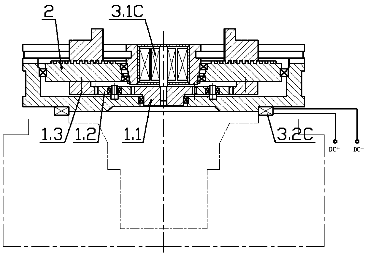
[0043] Such as image 3 As shown in a vertical lathe chuck, the resistance torque input mechanism includes a DC torque motor 3.1C arranged in the shaft center hole of the chuck body, wherein the housing of the DC torque motor 3.1C is connected to the shaft of the chuck body The center hole is connected, the motor shaft of the DC torque motor 3.1C is coaxially connected with the sun gear 1.1, the spiral groove disc 2 is connected with the ring gear 1.3 of the planetary reduction mechanism 1, and the planet carrier 1.2 is fixedly connected with the chuck body. The power input end of the DC torque motor 3.1C is connected with the chuck opening and closing control circuit of the lathe through the conductive slip ring connector 3.2C.
[0044] The chuck body is fixedly connected to the spindle of the lathe. The rotation of the spindle serves as the power source for the chuck to clamp or loosen the workpiece. The spindle of the lathe rotates forward or reverse, and the spiral groove ...
PUM
 Abstract
Description
Claims
Application Information
 - R&D
- Intellectual Property
- Life Sciences
- Materials
- Tech Scout
- Unparalleled Data Quality
- Higher Quality Content
- 60% Fewer Hallucinations
Browse by: Latest US Patents, China's latest patents, Technical Efficacy Thesaurus, Application Domain, Technology Topic, Popular Technical Reports.
© 2025 PatSnap. All rights reserved.Legal|Privacy policy|Modern Slavery Act Transparency Statement|Sitemap|About US| Contact US: help@patsnap.com


