Aircraft aerodynamic thermal protection system

A protection system, a technology for aircraft, applied in aircraft, flight direction control, motor vehicles and other directions, can solve the problems of low power demand, unsatisfactory, low cost performance, etc., to achieve effective utilization, simple overall structure, improve mobility and The effect of battlefield survivability

Inactive Publication Date: 2020-05-08
THE GENERAL DESIGNING INST OF HUBEI SPACE TECH ACAD
View PDF6 Cites 3 Cited by
  • Summary
  • Abstract
  • Description
  • Claims
  • Application Information

AI Technical Summary

Problems solved by technology

The passive response to aerodynamic heat is very effective and cheap for ultra-high-speed aircraft that face harsh aerothermal environments for a short period of time, but for ultra-high-speed aircraft that face harsh aerothermal environments for a long time, it will lead to a significant increase in negative quality and is not cost-effective
The core idea of ​​active response is to make full use of aerodynamic heat. At present, it can be seen that the report is to convert aerodynamic heat into electrical energy. However, for hyperspeed aircraft, the demand for electrical energy is not strong, and it is not ideal to deal with aerodynamic heat by thermoelectric conversion.

Method used


Image

  • Aircraft aerodynamic thermal protection system
  • Aircraft aerodynamic thermal protection system
  • Aircraft aerodynamic thermal protection system

Examples


Embodiment 1

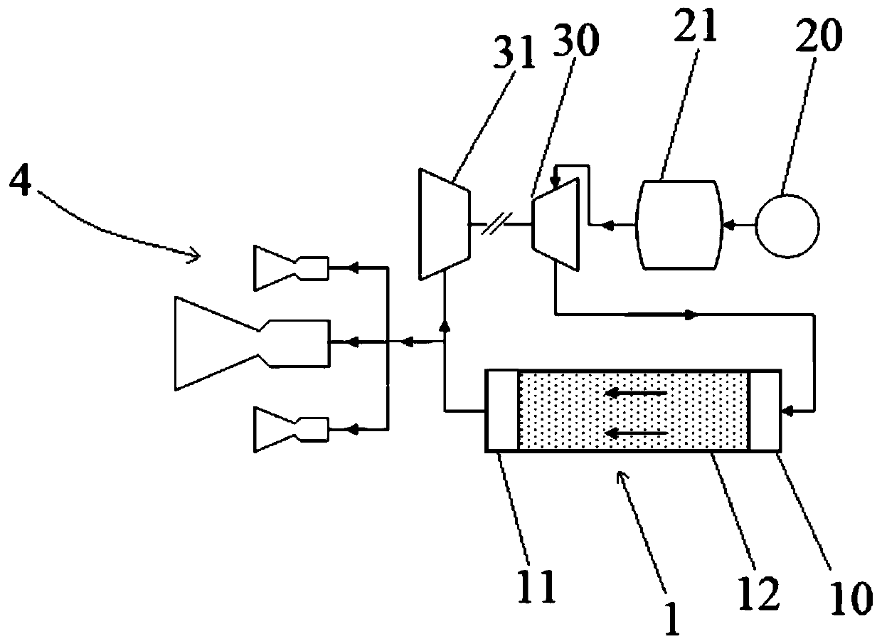
[0036] see figure 1 As shown, the embodiment of the present invention provides an aircraft aerodynamic thermal protection system, the system includes an aircraft main body 1, a first delivery assembly located upstream of the aircraft main body 1, a second delivery assembly and a drive assembly located downstream of the aircraft main body 1 4. Wherein, the first conveying assembly includes a low-pressure conveying member 20 and a storage member 21 located downstream of the low-pressure conveying member 20. There is a liquid cooling medium in the storing member 21. The low-pressure conveying member 20 is used to pressurize the cooling medium and move downstream Conveying, the second delivery assembly comprises a first pressurizing part 30 and a second pressurizing part 31, the first pressurizing part 30 is arranged between the storage part 21 and the aircraft main body 1, and the second pressurizing part 31 is arranged on the aircraft main body 1 Downstream, the first pressurizi...

Embodiment 2

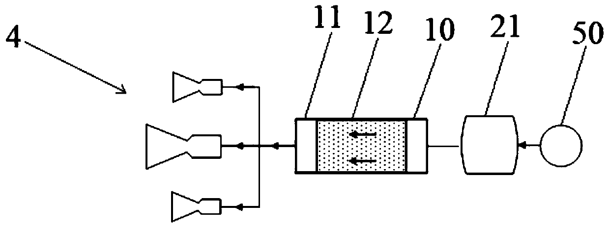
[0043] The present invention also provides an aircraft aerodynamic thermal protection system, see figure 2 As shown, the system includes an aircraft main body 1, a third delivery assembly located upstream of the aircraft main body 1 and a drive assembly 4 located downstream of the aircraft main body 1. The downstream storage part 21 contains a liquid cooling medium in the storage part 21. The pressurized delivery part 50 is used to pressurize the liquid cooling medium and deliver it to the aircraft main body 1. The cooling medium is used to absorb the heat from the outer wall of the aircraft main body 1. The heat is absorbed and vaporized, and the drive assembly 4 is used to receive the vaporized cooling medium and convert the internal energy of the cooling medium into kinetic energy to generate thrust.

[0044] Specifically, the pressurized conveying part 50 is a high-pressure bottle filled with nitrogen or helium, which is used to pressurize the cooling medium in the storag...


PUM


Abstract

The invention discloses an aircraft aerodynamic thermal protection system, and relates to the field of ultra-high-speed aircrafts. The aircraft aerodynamic thermal protection system comprises an aircraft body, a first conveying assembly, a second conveying assembly and a driving assembly. The first conveying assembly comprises a low-pressure conveying piece and a storage piece. The low-pressure conveying piece is used for pressurizing a cooling medium in the storage piece and then conveying the cooling medium downstream. The second conveying assembly comprises a first pressurizing piece and asecond pressurizing piece. The first pressurizing piece is used for further pressurizing the pressurized cooling medium and then conveying the pressurized cooling medium to the aircraft main body, wherein the cooling medium is used for absorbing heat of the outer wall of the aircraft body and is gasified after absorption. The second pressurizing piece is used for driving the first pressurizing piece through part of the gasified cooling medium. The driving assembly is used for converting the internal energy of the other part of the gasified cooling medium into kinetic energy to generate thrust.The aircraft aerodynamic thermal protection system provided by the invention can meet the aerodynamic thermal protection requirement in an aerodynamic thermal environment for a long time, and provides positive thrust or attitude control power for an aircraft.

Description

technical field [0001] The invention relates to the field of ultra-high-speed aircraft, in particular to an aircraft aerodynamic thermal protection system. Background technique [0002] Ultra-high-speed aircraft generally refers to aircraft with a flight speed exceeding 5 times the speed of sound. It has the characteristics of high speed, strong maneuverability, high precision, and ultra-long range. It is mainly used to strike decisive targets with strong time sensitivity and high value in tactical battles. [0003] When the aircraft flies in the atmosphere at hypersonic speed, the air around it will be strongly compressed and rubbed, and most of the kinetic energy will be converted into heat energy, causing the temperature of the air to rise sharply, and the heat energy will be quickly transferred to the surface of the aircraft. The heating phenomenon caused by high-speed flight in the atmosphere is called aerodynamic heating. Studies have shown that when the flight Mach n...

Claims


Application Information

Patent Timeline
Patent Type & Authority Applications(China)
IPC IPC(8): B64C15/14B64C30/00B64D27/02B64D45/00
CPCB64C15/14B64C30/00B64D27/02B64D45/00B64C15/02B64C1/38
Inventor 陈巍张斌方欢王涛峰王小雨石磊钟明磊李健黄峰周磊杨易
Owner THE GENERAL DESIGNING INST OF HUBEI SPACE TECH ACAD
Why Eureka
Try Eureka