
Self-assembly super-resolution optical probe based on fiber optical tweezers

An optical fiber optical tweezers and optical probe technology, applied in the field of nanophotonics, can solve the problems of large optical path, high cost, complex structure, etc., and achieve the effect of high flexibility

Inactive Publication Date: 2020-05-08
GUILIN UNIV OF ELECTRONIC TECH
View PDF8 Cites 11 Cited by
  • Summary
  • Abstract
  • Description
  • Claims
  • Application Information

AI Technical Summary

Problems solved by technology

[0007] However, the above-mentioned systems combining optical tweezers and optical nanofluidics are all based on the spatial optical tweezers system
The spatial optical tweezers system uses a lot of precision optical devices, the structure is complex, the optical path is large, and the cost is high

Method used


Image

  • Self-assembly super-resolution optical probe based on fiber optical tweezers
  • Self-assembly super-resolution optical probe based on fiber optical tweezers
  • Self-assembly super-resolution optical probe based on fiber optical tweezers

Examples


Embodiment 1

[0037] Embodiment 1: A super-resolution optical probe based on a coaxial double-ring multi-core fiber.

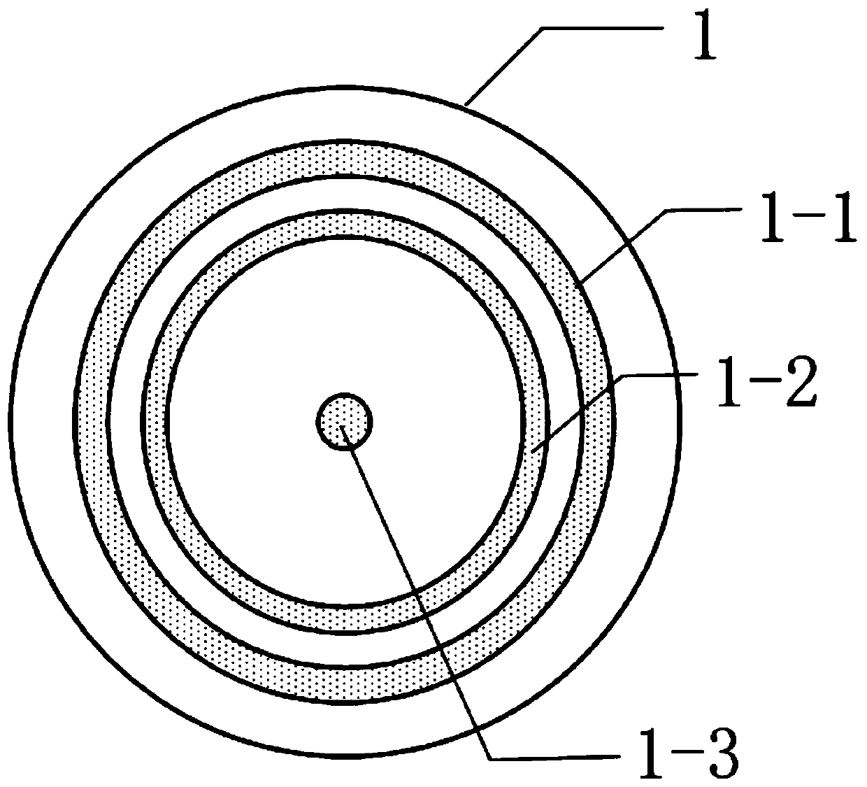
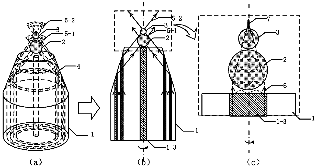
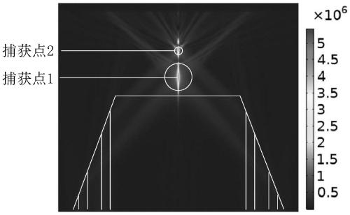
[0038] use as figure 1 The multi-core optical fiber 1 shown is taken as an example to illustrate the structure and principle of the present invention. The optical fiber has two coaxially distributed annular cores 1-1, 1-2 and an intermediate core 1-3. At the tip of the optical fiber 1, a rotationally symmetrical reflective frustum conical structure 4 is formed through precision grinding, such as figure 2 shown. The two annular fiber cores 1-1, 1-2 are used to transmit the captured light beams 5-1, 5-2 of 980nm, total reflection occurs on the slope of the truncated conical structure 4, converge outside the end face of the fiber, and converge in the axial direction of the fiber Two optical potential wells with high energy density are formed, which can stably trap two dielectric microspheres2,3. The middle fiber core 1-3 transmits a 532nm single-mode beam 6. After the bea...

Embodiment 2

[0044] Embodiment 1 presents a multi-core optical fiber with two coaxially distributed annular cores. Actually, the present invention is not limited to this kind of optical fiber. Such as Figure 9 The 5-core fiber shown 8 ( Figure 9 (a)) and 9-core fiber 9 ( Figure 9 (b)), this type of multi-core fiber also has a central core, the difference is that the other peripheral cores are located on two coaxially distributed circumferences. This type of multi-core optical fiber can also realize two stable trapping potential wells after preparing a symmetrical truncated cone at the fiber end, stably trap two dielectric microspheres, realize the compression of the middle fiber core beam, and form a super-resolution nano-optical probe.

Embodiment 3

[0046] Such as Figure 10 As shown, the intermediate core of the multi-core optical fiber adopted in the present invention can also be a two-layer waveguide structure, wherein the functions of the two outer ring cores are the same as those in the above-mentioned embodiment, and the inner layer core of the intermediate core is used for transmission. Based on the single-mode short-wavelength light generated by the nano-optical jet, the outer layer of the middle fiber core transmits a light beam with the same wavelength as the captured beam, which is used to adjust the capture position of the two microspheres, which can be adjusted by adjusting the distance between the two microspheres The spacing is used to adjust the two-stage compression effect of the two microsphere lenses on the intermediate core beam.


PUM

PropertyMeasurementUnit
refractive indexaaaaaaaaaa

Abstract

The invention provides a self-assembly type super-resolution optical probe based on fiber optical tweezers. The self-assembly type super-resolution optical probe is characterized by being composed ofa multi-core optical fiber double-optical-tweezers system and medium microspheres with two diameters. Specifically, the multi-core optical fiber is provided with a peripheral fiber core and a middle fiber core which are distributed in a circular symmetry mode, and an optical fiber end is provided with a symmetrical cone frustum structure, so that captured light beams transmitted in the peripheralfiber core are focused, and double optical tweezers are formed in the axial direction of the optical fiber and used for capturing the microspheres with two diameters in a cascading mode; the middle fiber core of the multi-core optical fiber transmits short-wavelength nanometer optical jet flow illumination light, light beams are emitted out of the optical fiber end and then irradiated on the microspheres captured in a cascade connection mode, and nanometer-scale-size optical jet flow is generated through two-stage compression of the microspheres. The self-assembly type super-resolution opticalprobe can be used for nanometer resolution optical detection, and can be widely applied to the field of super-resolution fluorescence detection and imaging.

Description

[0001] (1) Technical field [0002] The invention relates to a self-assembled super-resolution optical probe based on optical fiber optical tweezers, which can be used to generate nanometer-sized optical jets, break through the diffraction limit, and realize super-resolution optical illumination and detection, belonging to the technical field of nanophotonics. [0003] (2) Background technology [0004] Over the past few decades, different methods have been tried to overcome the limitations of optical microscopy imaging due to the Abbe diffraction limit. Several super-resolution optical imaging techniques, including scanning near-field optical microscopy, stimulated emission depletion microscopy, metamaterial metalens microscopy, solid immersion lens microscopy, and superoscillating lens microscopy, have been successfully achieved. Although they have good performance, they are expensive, lead to long preparation time, and detection methods are cumbersome. [0005] The optical ...

Claims


Application Information

Patent Timeline
Patent Type & Authority Applications(China)
IPC IPC(8): G02B6/26G02B6/32
CPCG02B6/262G02B6/32
Inventor 苑立波杨世泰
Owner GUILIN UNIV OF ELECTRONIC TECH
Learn More