
Electrical fire network monitoring, early warning, alarm and emergency control system and method

An electrical fire and emergency control technology, which is applied to fire alarms with electric effects, fire alarms and alarms that rely on smoke/gas effects, etc., can solve the problem that electrical fires cannot be prevented and electrical fires have not been completely resolved , unable to prevent problems such as remote emergency control fires, to achieve the effect of avoiding economic losses and preventing electrical fires

Active Publication Date: 2021-09-28
JIANGSU ONNES ELECTRIC POWER TECH CO LTD
View PDF8 Cites 0 Cited by
  • Summary
  • Abstract
  • Description
  • Claims
  • Application Information

AI Technical Summary

Problems solved by technology

However, the system can only play a role in remote monitoring, and cannot prevent and remotely control the occurrence of fires
At present, smart home collection terminals with remote control functions on the market, such as smart sockets, are mainly used to solve the problem of smart electricity consumption. By measuring voltage, current, and power consumption, they help users save electricity and remotely control the on-off of electrical equipment. But it can't play the role of preventing electrical fire
So far, the problem of electrical fires in small fields such as residential buildings and shops along the street has not been completely solved

Method used


Image

  • Electrical fire network monitoring, early warning, alarm and emergency control system and method
  • Electrical fire network monitoring, early warning, alarm and emergency control system and method
  • Electrical fire network monitoring, early warning, alarm and emergency control system and method

Examples


Embodiment 1

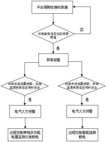
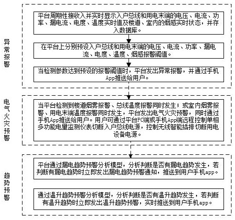
[0056] Example 1, the electrical fire network monitoring platform passes the long-awalation analysis model of the leakage, and the analysis is determined whether there is a leakage trend. If there is a leakage trend, it immediately issues a leakage trend warning notification, push it to the user's mobile phone APP, leakage trend warning analysis model calculation process as follows:

[0057] The platform traverses the historical data of the previous N days, and retrieves the maximum current I, then obtain the maximum current moment of leakage current I. L , The acquired data is made up.

[0058] Leakage current at the maximum current time for each day and the day after a new day L The division comparison is performed, and the N-1 leakage current coefficient is obtained is as follows:

[0059]

[0060] The maximum current I is divided by the maximum current I for two consecutive days, and the N-1 maximum current coefficient value is obtained is as follows:

[0061]

[0062] The...

Embodiment 2

[0069] Example 2, through temperature rise and warning analysis model, the analysis judgment has a temperature rise trend. If it is judged that there is a temperature rise warning, the temperature rise warning is sent to the user's mobile app in real time, the temperature rise and warning analysis The model calculation formula is as follows:

[0070] The platform traverses the historical data of the previous M days, M ≥ 2, retrieves the maximum current per day, then obtain the temperature value of the maximum current time, will make the dividing comparison comparison with the temperature value of the day before the day before, -1 temperature coefficient values ​​are as follows:

[0071]

[0072] The division comparison will be made to the maximum current I of the previous day after two consecutive days, and the M-1 current coefficient value is obtained is as follows:

[0073]

[0074] The platform is compared by the data comparison model, and the two adjacent leakage current c...

Embodiment 3

[0080] Example 3, the real-time current value greater than the insertion rated current of the platform is too large, and the platform issues a load overload alarm prompt.

[0081] Wireless smart plugging includes MCU control units, WiFi modules, power chips, temperature monitoring units, relays, MCU control units numbered each socket of the insertion, using the platform or mobile app into the electric device information connected through the platform or mobile app To form one-one mapping relationship with the plug-in per socket.

[0082] The temperature monitoring unit monitors the copper sheet temperature of the plug-in, the relay controls the power-off state of each socket, sets the temperature protection threshold in the MCU. When the plug-in detects a certain road, the junction temperature reaches the preset threshold, The plug-in automatically cuts the power supply. Set voltage, current, leakage, power protection threshold in the MCU, automatically cut off the total power sup...


PUM


Abstract

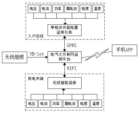
The invention discloses a system and method for electrical fire network monitoring, early warning, alarm and emergency control. The single-phase multi-functional electric power monitoring instrument in the control system is installed on the home bus, and various parameters on the home bus are collected in real time. The monitoring data is uploaded to the electrical fire network monitoring platform; the wireless smart plug-in strip is connected to the electrical equipment, and the parameters of the connected electrical equipment are collected in real time, and the real-time monitoring data and the power-off status information of the plug-in strip are uploaded to the electrical fire network monitoring platform ;The electrical fire network monitoring platform is used for real-time display, analysis, processing and collection of information, and real-time synchronization of the user's mobile phone APP. Users can remotely monitor single-phase multi-functional power monitoring instruments and wireless smart power strips through the electrical fire network monitoring platform PC or mobile phone APP. Perform power on and off control. The invention solves the problem of electrical fire control in nine small places such as residential houses, shops along the street, and family workshops, and three-in-one places, prevents electrical fires, and avoids unnecessary economic losses.

Description

Technical field [0001] The present invention relates to the field of electrical fire safety monitoring, and specific to electrical fire networking monitoring and early warning, alarm and emergency control system, method. Background technique [0002] With the continuous improvement of social living standards, a large number of household appliances continue to enter the resident families, become a necessity in our daily life. However, with the increasing number of household appliances, a large number of living electricity, potential electrical fire hazards are constantly rising, and many of the deep-minded fire accidents have occurred. Especially residential residential, along the street shop, family workshop, etc. For the hiking area of ​​the small fireman, most of the circuit faults, improper use of electrical appliances, electrical fires such as electricity safety hazards, so family homes, "three in one" The electrical fire management of "nine small" places has become a very im...

Claims


Application Information

Patent Timeline
Patent Type & Authority Patents(China)
IPC IPC(8): G08B17/10G08B17/06G08B25/10H02J13/00
CPCG08B17/06G08B17/10G08B25/10
Inventor 余成军张万新黄来宾顾配公张朝柱袁林山李荣安
Owner JIANGSU ONNES ELECTRIC POWER TECH CO LTD
Learn More