

Machining equipment used for foamed concrete
A technology of foamed concrete and processing equipment, which is applied to clay preparation devices, chemical instruments and methods, cement mixing devices, etc., which can solve problems such as single function, poor mixing effect, and low efficiency, and achieve improved foaming efficiency and full mixing Effect
- Summary
- Abstract
- Description
- Claims
- Application Information
AI Technical Summary
Problems solved by technology
Method used
Image

Examples
Embodiment 1
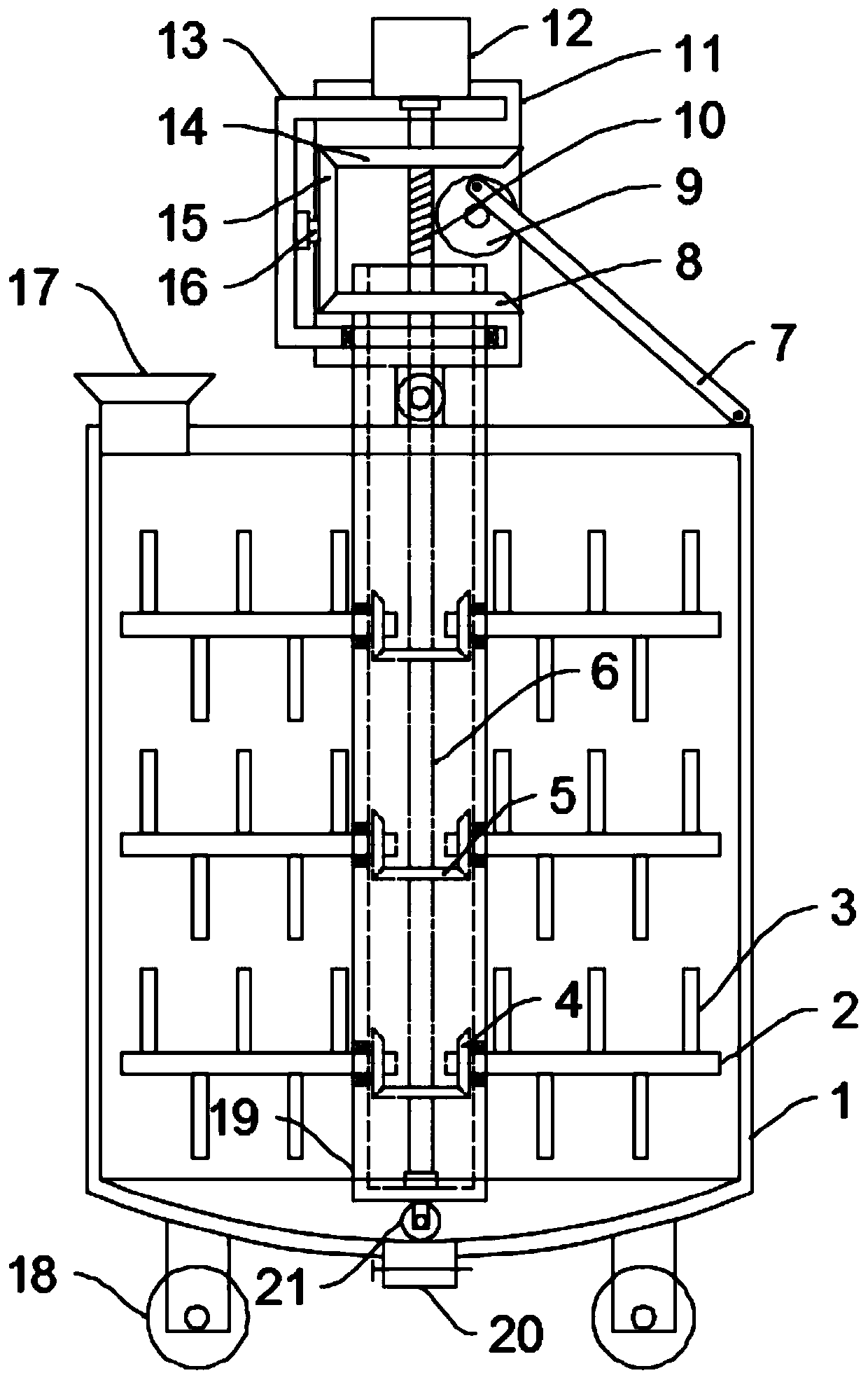
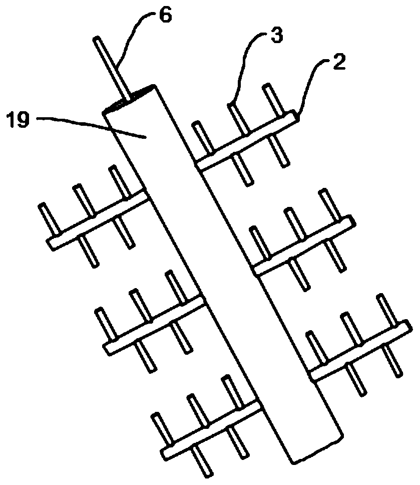
[0023] see Figure 1~2 , in an embodiment of the present invention, a processing equipment for foamed concrete, including a cylinder 1 and a mixing assembly, the bottom of the cylinder 1 is spherical, the center of the sphere is located at the top of the cylinder 1, and the cylinder 1 The bottom is evenly and symmetrically fixed with support legs, and the bottom of the support legs is equipped with rollers 18, the rollers 18 are self-locking rollers, which facilitate the movement of the device, and the top side of the cylinder 1 is provided with a feed hopper 17, the cylinder There is a discharge port 20 in the middle of the bottom of the body 1, and a valve is installed on the discharge port 20. The stirring assembly includes a mounting column 19, a rotating shaft 6, a first bevel gear 5, a second bevel gear 4, a stirring rod 2, a stirring support Rod 3, mounting bracket 13, mounting plate 11, motor 12, driving bevel gear 14, driving bevel gear 15, driven bevel gear 8, worm s...
Embodiment 2
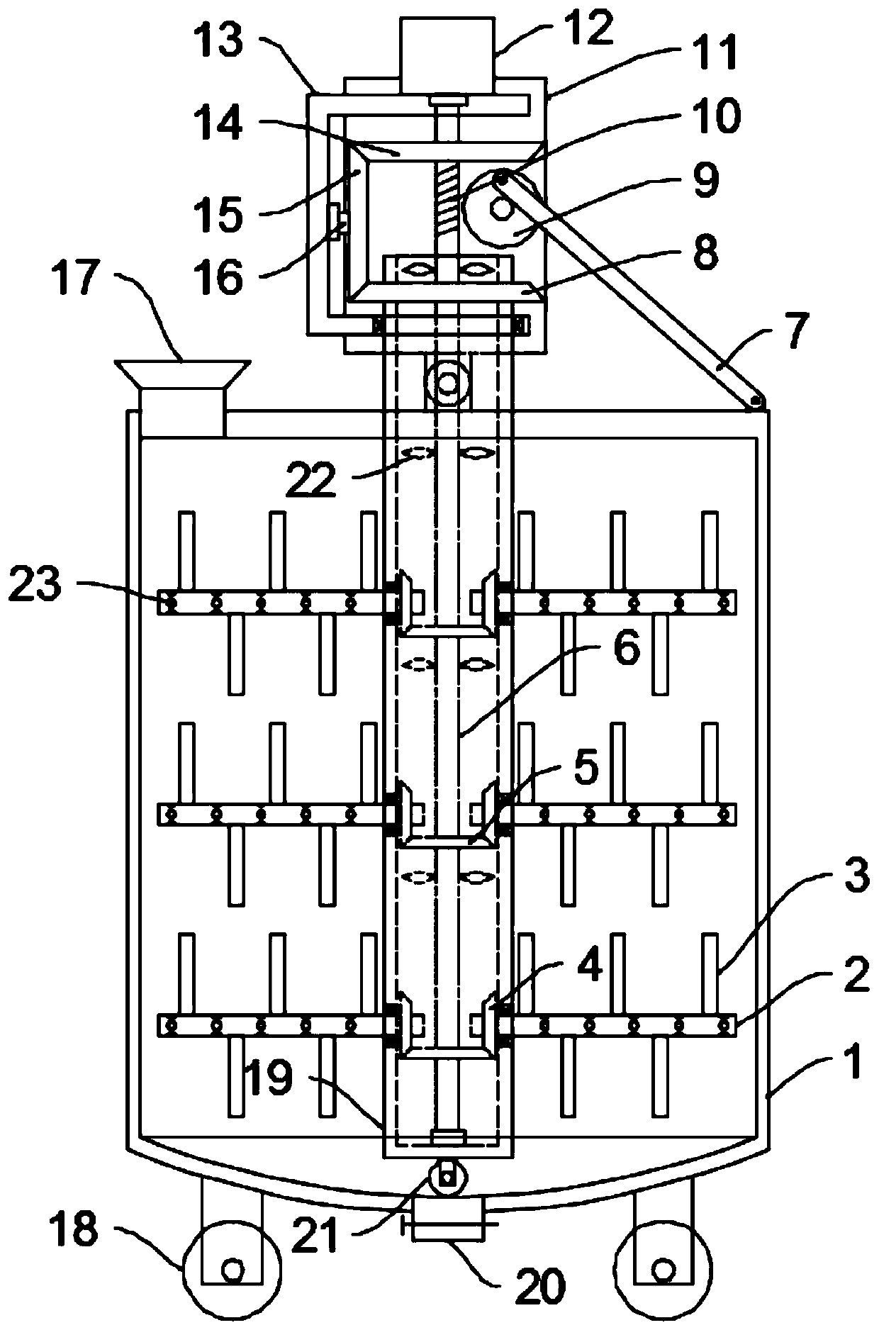
[0026] see image 3 The difference between the embodiment of the present invention and the embodiment 1 is that the top of the mounting column 19 is open, the rotating shaft 6 is installed with a plurality of suction fan blades 22 at intervals from top to bottom, and the inside of the stirring rod 2 is hollow and One end opening in the installation column 19, the stirring rod 2 is evenly provided with a plurality of aeration holes 23 on the rod section outside the installation column 19, when the rotating shaft 6 rotates, wind is generated by the suction fan blade 22, and the wind enters the installation column 19 and then Into the stirring rod 2 and finally ejected from the aeration hole 23 to generate more bubbles, further improving the foaming efficiency.
[0027]The working principle of the present invention is: when working, put the raw material into the barrel 1, start the motor 12, the motor 12 drives the rotating shaft 6 to rotate, the rotating shaft 6 drives the drivi...
PUM
 Abstract
Description
Claims
Application Information