
Thermal power generating unit fused salt step energy storage and discharge peak regulating system and method

A technology of thermal power units and molten salt, which is applied to mechanical equipment, steam engine devices, machines/engines, etc., and can solve problems such as large energy loss

Pending Publication Date: 2020-05-12
CHINA POWER ENG CONSULTING GRP CORP EAST CHINA ELECTRIC POWER DESIGN INST
View PDF0 Cites 12 Cited by
  • Summary
  • Abstract
  • Description
  • Claims
  • Application Information

AI Technical Summary

Problems solved by technology

[0007] The invention solves the problem that the molten salt energy storage system in the related art is used in a single stage, resulting in a large energy loss, and proposes a thermal power unit molten salt cascade storage and discharge energy peak regulation system and method

Method used


Image

  • Thermal power generating unit fused salt step energy storage and discharge peak regulating system and method
  • Thermal power generating unit fused salt step energy storage and discharge peak regulating system and method
  • Thermal power generating unit fused salt step energy storage and discharge peak regulating system and method

Examples


Embodiment 1

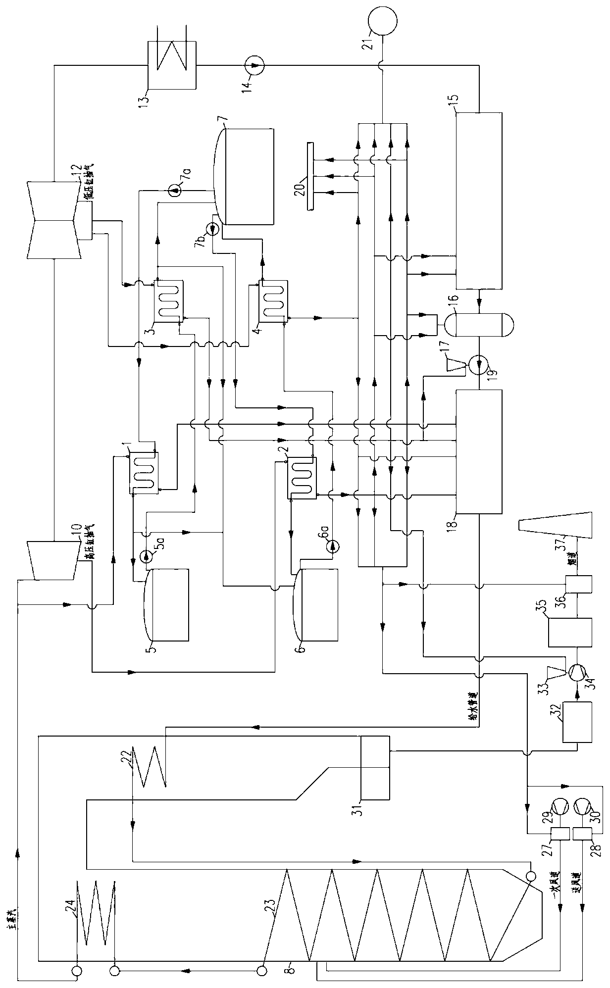
[0045] The thermal power unit in this embodiment is a non-reheating unit.

[0046] Such as figure 1 As shown, a thermal power unit molten salt cascade energy storage and discharge system includes a thermal power unit and a molten salt cascade energy storage system.

[0047] Among them, the thermal power unit includes boiler 8, main steam turbine, condenser 13, condensate pump 14, feed water pump 19, heat recovery system, feed water pump small steam turbine 17, auxiliary steam pipeline 20, induced draft fan small steam turbine 33 and flue gas system, boiler 8 Connect the main steam turbine through the steam pipeline, output the main steam to the main steam turbine, and heat the low-temperature reheated steam from the main steam turbine to the high-temperature reheated steam and send it back to the main steam turbine; The thermal system is recycled; the boiler 8 is connected to the heat recovery system through the water supply pipe, and the boiler 8 is connected to the flue gas...

Embodiment 2

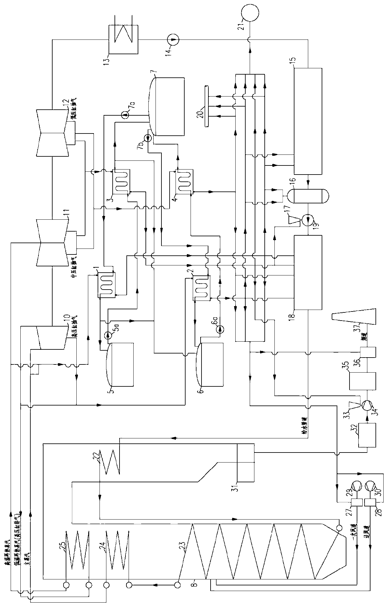
[0059] The thermal power unit in this embodiment is a once-reheating unit.

[0060] Such as figure 2 As shown, a thermal power unit molten salt cascade energy storage and discharge system includes a thermal power unit and a molten salt cascade energy storage system.

[0061] Among them, the thermal power unit includes boiler 8, main steam turbine, condenser 13, condensate pump 14, feed water pump 19, heat recovery system, feed water pump small steam turbine 17, auxiliary steam pipeline 20, induced draft fan small steam turbine 33 and flue gas system, boiler 8 Connect the main steam turbine through the steam pipeline, output the main steam to the main steam turbine, and heat the low-temperature reheated steam from the main steam turbine to the high-temperature reheated steam and send it back to the main steam turbine; The thermal system is recycled; the boiler 8 is connected to the heat recovery system through the water supply pipe, and the boiler 8 is connected to the flue g...

Embodiment 3

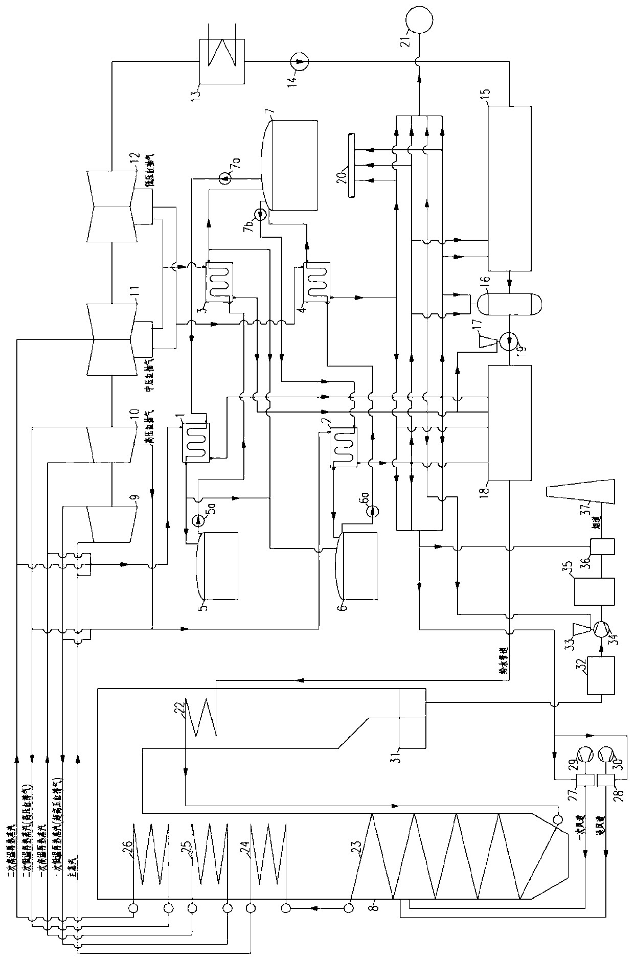
[0073] In this embodiment, the thermal power unit is a double reheat unit.

[0074] Such as image 3 As shown, a thermal power unit molten salt cascade energy storage and discharge system includes a thermal power unit and a molten salt cascade energy storage system.

[0075] Among them, the thermal power unit includes boiler 8, main steam turbine, condenser 13, condensate pump 14, feed water pump 19, heat recovery system, feed water pump small steam turbine 17, auxiliary steam pipeline 20, induced draft fan small steam turbine 33 and flue gas system, boiler 8 Connect the main steam turbine through the steam pipeline, output the main steam to the main steam turbine, and heat the low-temperature reheated steam from the main steam turbine to the high-temperature reheated steam and send it back to the main steam turbine; The thermal system is recycled; the boiler 8 is connected to the heat recovery system through the water supply pipe, and the boiler 8 is connected to the flue ga...


PUM


Abstract

The invention relates to the technical field of fused salt energy storage, in particular to a thermal power generating unit fused salt step energy storage and discharge peak regulating system and method. The thermal power generating unit fused salt step energy storage and discharge peak regulating system comprises a thermal power generating unit and a fused salt step energy storage and discharge system. The thermal power generating unit comprises a boiler, a main turbine, a condenser, a condensate pump, a water feed pump, a regenerative system, a water feeding pump small turbine, an auxiliarysteam pipeline, a induced draft fan small turbine and an air and flue gas system. The fused salt step energy storage and discharge system comprises a high-temperature steam-fused salt heat exchanger set, a low-temperature steam-fused salt heat exchanger set, a high-temperature fused salt-steam heat exchanger set, a low-temperature fused salt-steam heat exchanger set, a high-temperature hot fused salt tank, a low-temperature hot fused salt tank and a cold fused salt tank. When the thermal power generating unit operates at low loads, the heat of redundant steam is stored to high-temperature andlow-temperature hot fused salt in a step manner, and the steam releasing heat is subjected to step utilization; and when the load need of the unit is high, the heat of the high-temperature and low-temperature hot fused salt is released to unit steam in a step manner is subjected to step utilization, the utilization rate of the equipment is increased, and the power generation efficiency, safe reliability and economical efficiency of the equipment are improved.

Description

technical field [0001] The invention relates to the technical field of molten salt energy storage, in particular to a thermal power unit molten salt cascade storage and discharge energy peak regulation system and method. Background technique [0002] The energy revolution aims to promote the sustainable development of energy, promote the development of new energy and the clean and efficient use of fossil energy. The rapid increase in the volume of new energy forces the load rate of traditional thermal power units to decrease. Most units operate at sub-full load for a long time, and a few even shut down, resulting in a waste of resources that have been put into production; The reduction of the overall load demand makes the load of the unit further reduced during the valley power period, which is close to the minimum steady load of the thermal power unit. These changes will lead to low utilization rate of thermal power units in production, low power generation efficiency, inc...

Claims


Application Information

Patent Timeline
IPC IPC(8): F01K7/16F01K11/02F01K17/02F01K3/00F01K13/00
CPCF01K7/16F01K11/02F01K17/02F01K3/00F01K13/00
Inventor 夏云飞叶勇健林磊蒋健邓文祥姚向昱
Owner CHINA POWER ENG CONSULTING GRP CORP EAST CHINA ELECTRIC POWER DESIGN INST
Learn More