
Crystal oscillation circuit and method and electronic equipment

A technology of crystal oscillation and crystal oscillator, applied in the direction of electrical components, impedance networks, etc., can solve the problems of waste of resources, long start-up time, failure to work, etc., to save time and resources, shorten start-up time, and prolong use The effect of longevity

Pending Publication Date: 2020-05-15
PHYPLUS INC
View PDF0 Cites 4 Cited by
  • Summary
  • Abstract
  • Description
  • Claims
  • Application Information

AI Technical Summary

Problems solved by technology

However, the inventors have found that there are at least the following problems in the prior art: generally used crystal oscillators have the disadvantage of slow start-up, and take a long time to complete the start-up, generally between several milliseconds to tens of milliseconds, wasting time; And in this process, the crystal oscillator only consumes power and cannot work, which wastes resources. As a result, the chip can only start working after the crystal oscillator starts to vibrate, which affects the working efficiency of the chip.

Method used


Image

  • Crystal oscillation circuit and method and electronic equipment
  • Crystal oscillation circuit and method and electronic equipment
  • Crystal oscillation circuit and method and electronic equipment

Examples


Embodiment Construction

[0018] In order to make the purpose, technical solutions and advantages of the embodiments of the present invention more clear, various implementation modes of the present invention will be described in detail below in conjunction with the accompanying drawings. However, those of ordinary skill in the art can understand that, in each implementation manner of the present invention, many technical details are provided for readers to better understand the present application. However, even without these technical details and various changes and modifications based on the following implementation modes, the technical solution claimed in this application can also be realized. The division of the following embodiments is for the convenience of description, and should not constitute any limitation to the specific implementation of the present invention, and the various embodiments can be combined and referred to each other on the premise of no contradiction.

[0019] The first embodi...


PUM


Abstract

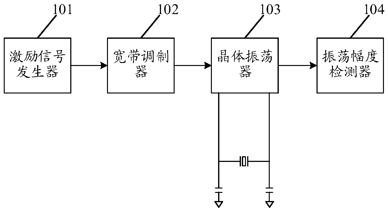
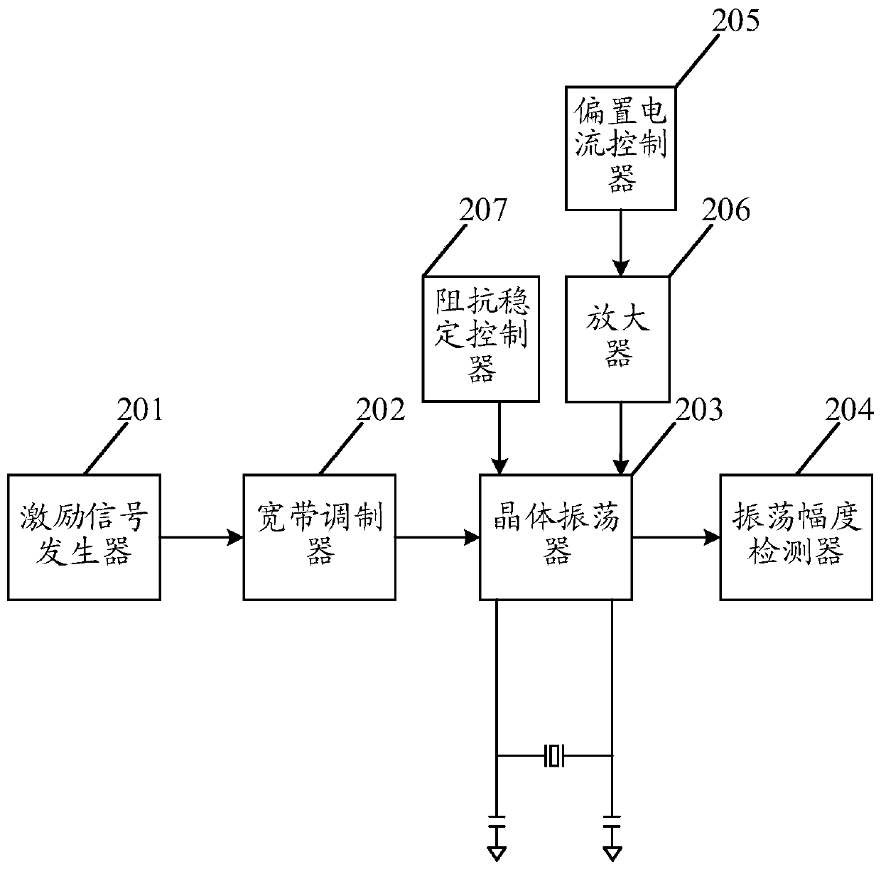
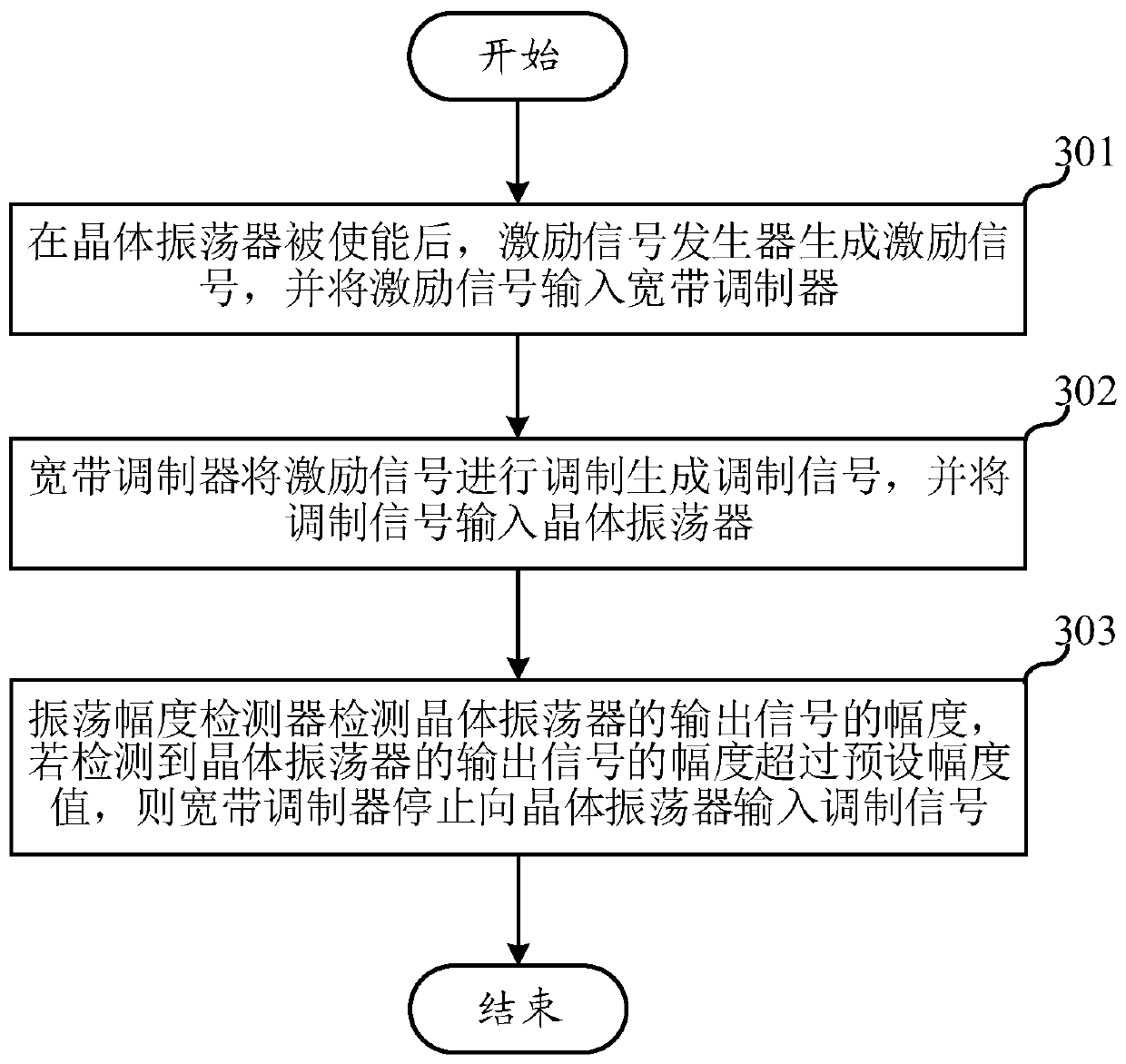
The embodiment of the invention relates to the field of circuit design, and particularly relates to a crystal oscillation circuit and method and electronic equipment. The crystal oscillation circuit disclosed by the invention comprises an excitation signal generator, a broadband modulator and an oscillation amplitude detector, wherein the excitation signal generator is used for generating an excitation signal after a crystal oscillator is enabled, and inputting the excitation signal into the broadband modulator; the broadband modulator is used for modulating the excitation signal to generate amodulation signal and inputting the modulation signal into the crystal oscillator, and the difference between the frequency of the modulation signal and the frequency of the crystal oscillator is within a preset range; the oscillation amplitude detector is used for detecting the amplitude of an output signal of the crystal oscillator, and if the amplitude of the output signal of the crystal oscillator exceeds a preset amplitude value, the broadband modulator stops inputting the modulation signal to the crystal oscillator. According to the invention, by shortening the oscillation starting timeof the crystal oscillator and reducing the average consumption of the circuit, rapid oscillation starting is realized, resources are saved, and the service life of the device is prolonged.

Description

technical field [0001] The embodiments of the present invention relate to the field of circuit design, in particular to a crystal oscillation circuit, method and electronic equipment. Background technique [0002] A crystal oscillator refers to a thin slice (referred to as a wafer) cut from a quartz crystal at a certain azimuth angle, and an IC is added inside the package to form a crystal component of an oscillator circuit. Quartz crystal resonators are referred to as quartz crystals or crystals. Because the quartz crystal has a very high quality factor, the quartz crystal oscillator can generate an oscillation waveform with accurate frequency and stability, and is widely used in clocks and watches, military industry, communication and other fields that require high oscillation frequency. [0003] In recent years, the design requirements for low-power and low-cost integrated circuits in various fields have become increasingly prominent. The chip of the integrated circuit h...

Claims


Application Information

Patent Timeline
IPC IPC(8): H03H9/19H03H9/125
CPCH03H9/19H03H9/125
Inventor 王肖
Owner PHYPLUS INC
Learn More