Balance control device for spray boom arms of high-ground-clearance boom sprayer
A boom spraying and balance control technology, which is applied to the device for catching or killing insects, application, animal husbandry, etc. It can solve the problems of long-term violent shaking of the end of the boom arm and affect the effect of spraying, and realizes automatic operation. , eliminate the influence, improve the effect of operation accuracy
- Summary
- Abstract
- Description
- Claims
- Application Information
AI Technical Summary
Problems solved by technology
Method used
Image
Examples
Embodiment 1
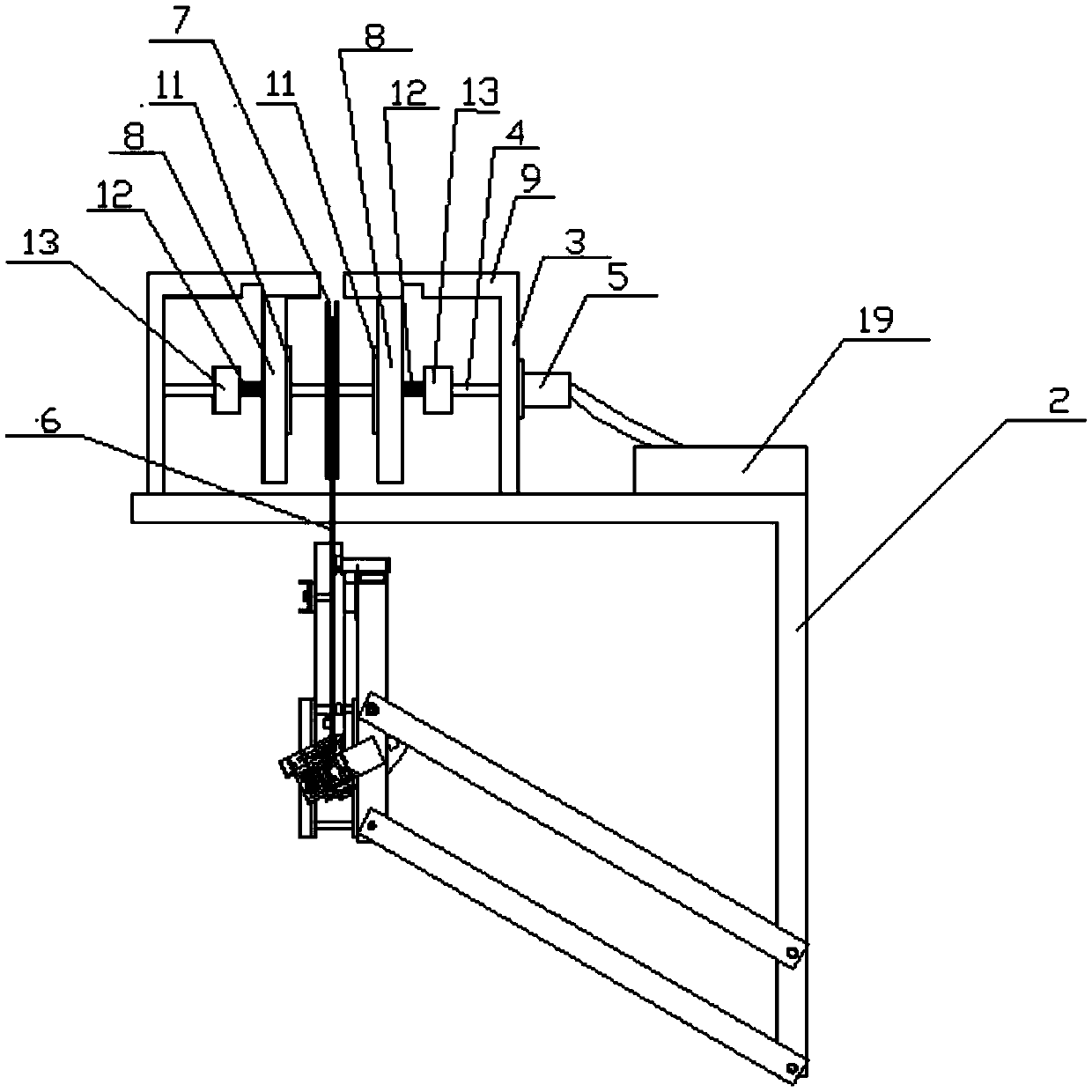
[0036] Example 1, such as Figure 1-Figure 5 As shown, a high ground clearance boom sprayer boom arm balance control device includes a bracket 3, a support shaft 4 mounted on the bracket 3, a drive motor 5 for driving the support shaft 4 to rotate, and a cable mounted on the support shaft 4 Recovery wheel 7 and coil spring assembly 8, and the circumferential limiter 9 that is fixed on the support 3, the circumferential limiter 9 can limit the circumferential direction of one end of coil spring assembly 8, so that coil spring assembly 8 can be rotated to tighten.
[0037]A cable 6 is wound on the cable recovery wheel 7, one end of the cable 6 is fixed to the cable recovery wheel 7, and the other end of the cable 6 is fixed to the end of the spray boom arm 1; when the end of the spray boom arm 1 moves downward, the cable 6 is pulled out , the coil spring assembly 8 is gradually tightened, when the end of the boom arm 1 moves upward, the drive motor 5 drives the support shaft 4 ...
Embodiment 2
[0042] Embodiment 2. In Embodiment 1, when the end of the spray boom arm 1 moves downward, the coil spring assembly 8 is tightened. Since the axial relative position of the coil spring assembly 8 and the cross bar remains unchanged, when the spray boom When the end of the arm 1 moves upward, the coil spring assembly 8 reverses along with the support shaft 4, and when the raised stopper 10 is stuck on the cross bar again, the large diameter end of the outer edge of the coil spring assembly 8 will be gradually enlarged Even disconnected, this will greatly shorten the service life of the coil spring assembly 8, and the reverse extension of the coil spring assembly will hinder the drive motor to drive the cable recovery wheel to recover the cable, affecting the tightening of the spray boom arm when it vibrates downward again Force, so this embodiment is improved as follows: on the basis of embodiment 1, as Figure 6-Figure 9 As shown, the device also includes a baffle 11, a telesc...
Embodiment 3
[0046] Embodiment 3, on the basis of embodiment 2, as Figure 5-Figure 7 As shown, the cross bar is provided with a groove 14, the groove 14 is suitable for the passage of the raised block 10, that is, the groove 14 can increase the surface distance between the cross bar and the coil spring assembly 8, so that the raised block 10 Can pass through the groove 14, when the end of the boom arm 1 moves upwards, the axial distance between the coil spring assembly 8 and the groove 14 and the electromagnet 13 is the same, that is, the outer large-diameter end of the coil spring assembly 8 can follow the The support shaft 4 rotates. The opening of the groove 14 faces the coil spring assembly 8, and the groove 14 runs through front and back, that is, it penetrates in the direction of rotation of the coil spring assembly 8, so that the coil spring assembly 8 can pass through when it moves to the axial position of the groove 14. Rotate circumferentially through the groove 14, and the sur...
PUM
 Abstract
Description
Claims
Application Information
 - R&D
- Intellectual Property
- Life Sciences
- Materials
- Tech Scout
- Unparalleled Data Quality
- Higher Quality Content
- 60% Fewer Hallucinations
Browse by: Latest US Patents, China's latest patents, Technical Efficacy Thesaurus, Application Domain, Technology Topic, Popular Technical Reports.
© 2025 PatSnap. All rights reserved.Legal|Privacy policy|Modern Slavery Act Transparency Statement|Sitemap|About US| Contact US: help@patsnap.com


