Eureka AIR delivers breakthrough ideas for toughest innovation challenges, trusted by R&D personnel around the world.

Precision part machining numerical control machine tool

A technology of precision parts and CNC machine tools, applied in metal processing, metal processing equipment, metal processing mechanical parts, etc., can solve the problems of reducing cutting stability and cutting quality, reducing tool rigidity, etc., to achieve a compact and compact overall structure. Small, flexible effect

Pending Publication Date: 2020-05-19
昂拓科技(苏州)有限公司
View PDF3 Cites 4 Cited by
  • Summary
  • Abstract
  • Description
  • Claims
  • Application Information

AI Technical Summary

Problems solved by technology

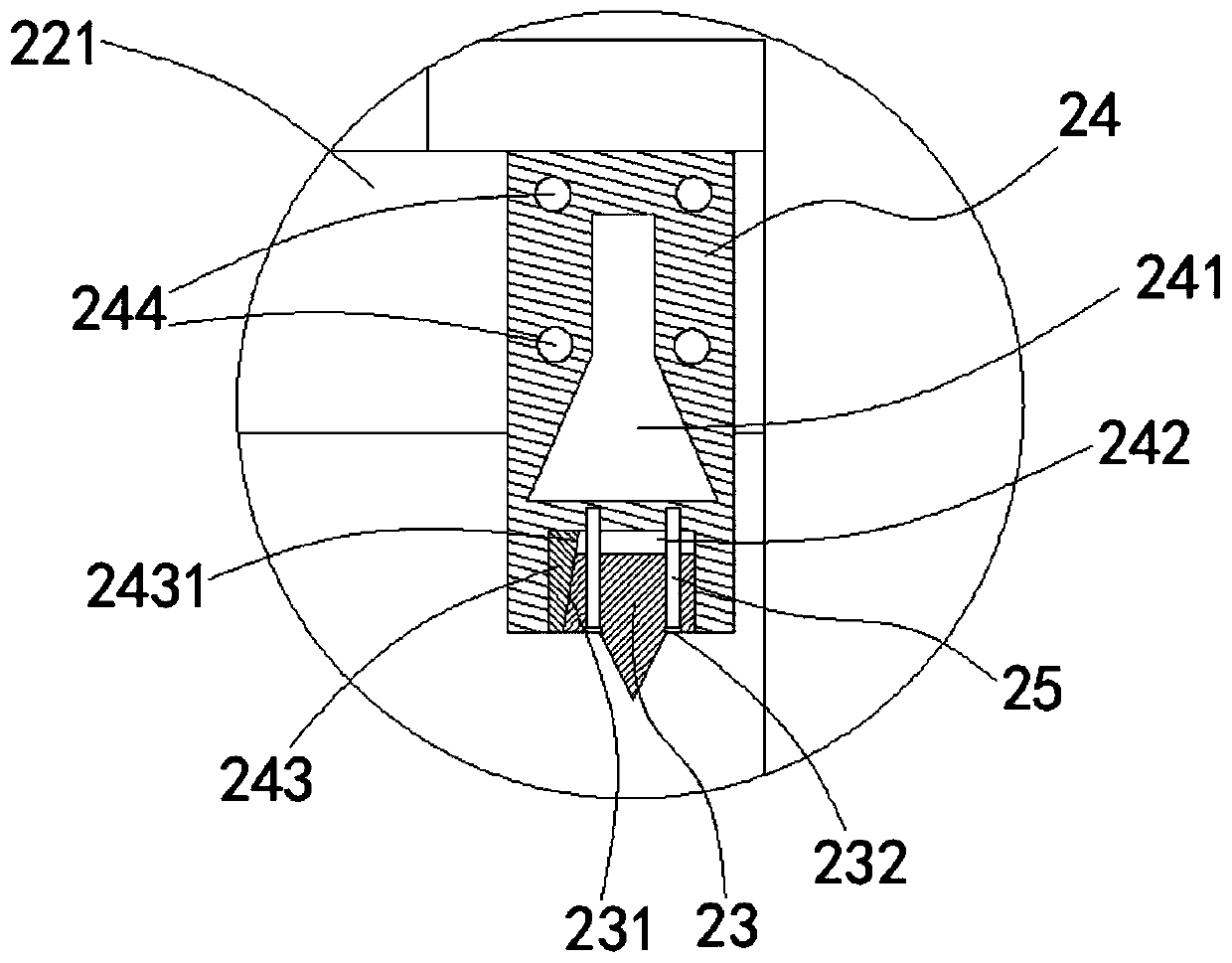
[0005] As disclosed in the application number 201820526251.7, a machine tool rotary tool holder device includes a rotary body and a structure for driving the rotary body to rotate. A set of cutter sleeves are arranged on the rotary body, and the lengths of the cutter sleeves are the same. In actual processing, the cutting edges of the cutters installed on the rotary body often need different heights to achieve continuous processing at different positions. Since the cutter sleeves are all of the same size, this requires the cutters to have different lengths. At this time The length of some tools needs to be set very long, resulting in a decrease in the rigidity of the tool, which greatly reduces the cutting stability and cutting quality

Method used


Image

  • Precision part machining numerical control machine tool
  • Precision part machining numerical control machine tool
  • Precision part machining numerical control machine tool

Examples


Embodiment Construction

[0046] Objects, advantages and features of the present invention will be illustrated and explained by the following non-limiting description of preferred embodiments. These embodiments are only typical examples of applying the technical solutions of the present invention, and all technical solutions formed by adopting equivalent replacements or equivalent transformations fall within the protection scope of the present invention.

[0047] In the description of the scheme, it should be noted that the terms "center", "upper", "lower", "left", "right", "front", "rear", "vertical", "horizontal", " The orientation or positional relationship indicated by "inner", "outer", etc. is based on the orientation or positional relationship shown in the drawings, and is only for the convenience of description and simplification of description, rather than indicating or implying that the device or element referred to must have a specific orientation , constructed and operated in a particular or...


PUM


Abstract

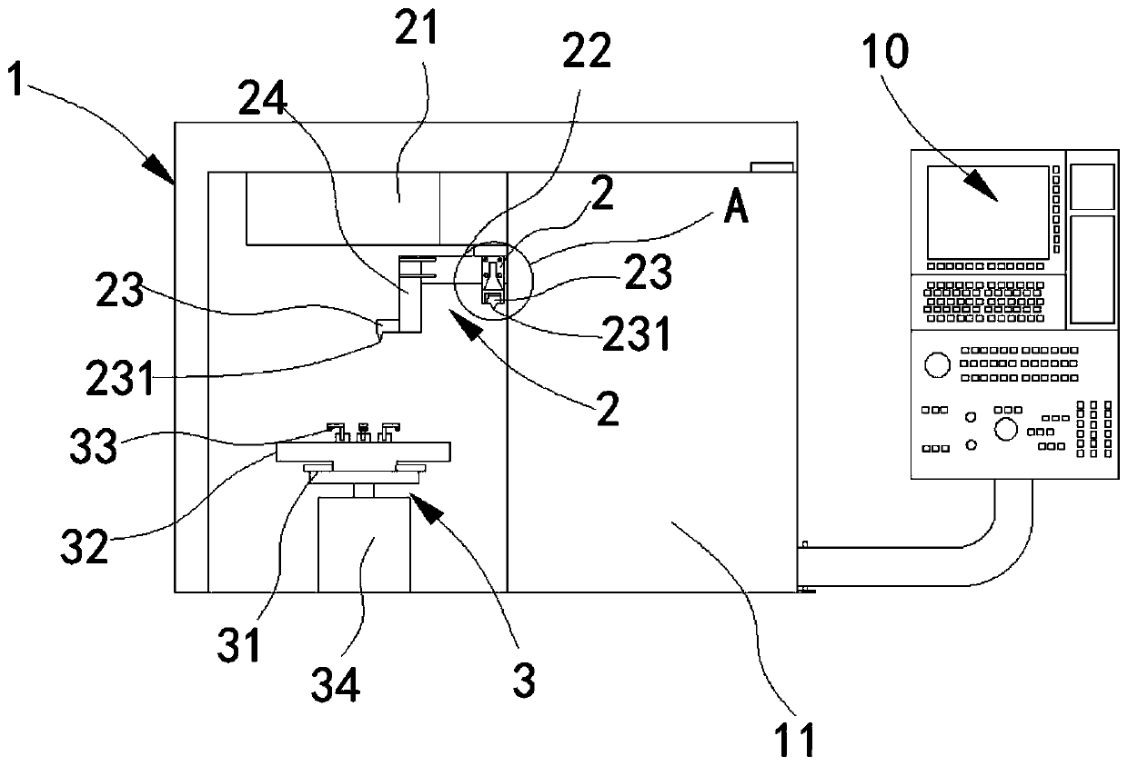
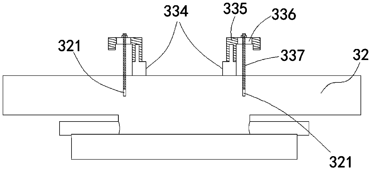
The invention discloses a precision part machining numerical control machine tool. The precision part machining numerical control machine tool comprises a machining chamber with an inner cavity. A workpiece machining device and a workpiece fixing and rotating mechanism are arranged in the machining chamber. The workpiece machining device comprises a moving mechanism and a turret capable of being driven to move and rotate by the moving mechanism. A plurality of machining tools are arranged on the turret. Cutting edges of at least two of the machining tools have the height difference. At least part of the machining tools of which the cutting edges have the height difference are detachably connected with the turret through different lengths of tool aprons. According to the precision part machining numerical control machine tool, the machining tools are fixed to the turret through the tool aprons with the different lengths; the requirement for the low position of the cutting edges of the machining tools can be met through the tool aprons; and accordingly, the length of the machining tool can be greatly reduced to ensure the rigidity of the tools, and the machining stability and qualitycan be improved.

Description

technical field [0001] The invention relates to the field of machine tools, in particular to a numerically controlled machine tool for machining precision parts. Background technique [0002] CNC machine tool is the abbreviation of numerical control machine tool, which is an automatic machine tool equipped with a program control system. The control system can logically process programs with control codes or other symbolic instructions, decode them, express them in coded numbers, and input them into the numerical control device through the information carrier. After calculation and processing, various control signals are sent by the numerical control device to control the movement of the machine tool, and the parts are automatically processed according to the shape and size required by the drawing. [0003] Some CNC machine tools include a processing chamber, a workpiece fixing mechanism, a turret tool holder, a structure for driving the turret tool holder to move, a control...

Claims


Application Information

Patent Timeline
Patent Type & Authority Applications(China)
IPC IPC(8): B23Q37/00B23B29/32B23B31/103B23B31/30B23Q11/00B23Q11/10B01D46/00B01D53/26
CPCB23Q37/00B23B29/32B23B31/30B23B31/103B23Q11/00B23Q11/10B01D53/261B01D53/265B01D46/58Y02P70/10
Inventor 许惠明肖荣鑫
Owner 昂拓科技(苏州)有限公司
Why Eureka
Eureka Blog
Learn More