FRP truss joint structure and implementation method thereof

A node structure and truss technology, which is applied to truss structures, truss beams, building structures, etc., can solve the problems of asynchronous colloid and bolt stress, and high requirements for component surface treatment, so as to achieve high construction efficiency and less welding workload , the effect of improving the bearing capacity

Active Publication Date: 2020-05-19
SOUTHEAST UNIV
View PDF8 Cites 3 Cited by
  • Summary
  • Abstract
  • Description
  • Claims
  • Application Information

AI Technical Summary

Problems solved by technology

[0009] Purpose of the invention: The purpose of the present invention is to provide a FRP truss node structure and its implementation method, which overcomes the asynchronous stress of the colloid and bolts in the traditional glue bolt connection method, and the surface treatment requirements of the components in the pre-tightening force tooth connection method It has the advantages of tight connection, high joint bearing capacity, high rigidity, easy construction and good durability, etc., and has high promotion value.

Method used


Image

  • FRP truss joint structure and implementation method thereof
  • FRP truss joint structure and implementation method thereof
  • FRP truss joint structure and implementation method thereof

Examples


Embodiment Construction

[0034] In order to further illustrate the present invention, the present invention will be further described below in conjunction with the examples and accompanying drawings, but it should not be understood as a limitation of the protection scope of the present invention.

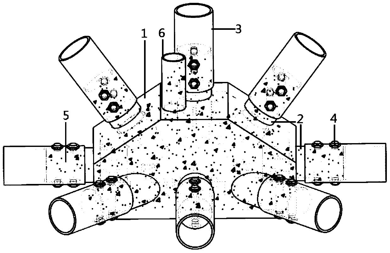
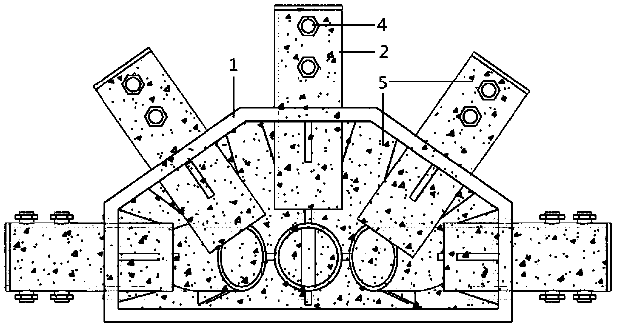
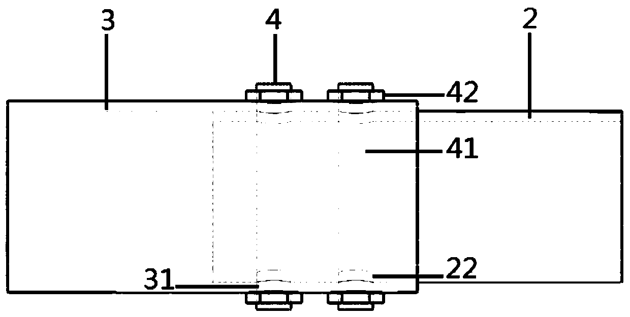
[0035] Such as Figure 1-4 As shown: a FRP truss node structure implemented in this implementation includes a steel box 1, a steel pipe 2 inserted into the steel box 1 at one end, an FRP pipe 3 with the same inner diameter as the outer diameter of the steel pipe 2, and a bolt for connecting the steel pipe 2 and the FRP pipe 3 Nail 4, micro-expansion concrete 5 poured into the steel box 1 and steel pipe 2, conduit 6 for pouring micro-expansion concrete 5 into the steel box 1 and steel pipe 2.

[0036] The steel box 1 has a plurality of tunnels 11 , wherein the number, shape and size of the tunnels 11 are determined according to the number, shape and size of the steel pipes 2 and the conduits 6 .

[0037] Th...


PUM


Abstract

The invention discloses an FRP truss joint structure and an implementation method thereof. The FRP truss joint structure comprises a steel box, steel pipes, FRP pipes, studs, micro-expansion concreteand a guide pipe, wherein the steel box is provided with a plurality of holes; and one ends of the steel pipes are inserted into the FRP pipes, and the other ends of the steel pipes extend into the steel box and are welded. A plurality of holes are formed in the pipe wall contact positions of the steel pipes and the FRP pipes in the pipe axis direction; the studs penetrate through the holes and are used for connecting and fixing the FRP pipes and the steel pipes; and the guide pipe is used for pouring the micro-expansion concrete into the steel box and the steel pipes. The circumferential stress generated by the micro-expansion concrete and the studs act together, so that the steel pipes cling to the inner walls of the FRP pipes; the parts, in the steel pipes, of the studs are surrounded by the expansion concrete to form shear pieces, and the connection of the steel pipes and the micro-expansion concrete is enhanced; and the compressive strength and durability of the micro-expansion concrete are increased through the constraint of the steel box and the steel pipes. The FRP truss joint structure has the advantages of high bearing capacity, large rigidity, good durability and the like.

Description

technical field [0001] The invention belongs to the fields of structural engineering and bridge engineering, and in particular relates to an FRP truss node structure and an implementation method thereof. Background technique [0002] Fiber Reinforced Polymer (FRP, Fiber Reinforced Polymer) is widely used in various fields of civil engineering due to its light weight, high strength, corrosion resistance and other advantages. FRP pipe truss is a new type of building structure that has emerged in recent years. During use, the rods are in a one-way, full-section stress state, which can give full play to the characteristics of high strength and rigidity of composite materials along the fiber direction. [0003] The traditional connection methods of steel truss nodes include welding and high-strength bolt connection. However, due to the characteristics of FRP materials, such as the relatively low elastic modulus of GFRP (Glass Fiber Reinforced Polymer), after connecting with high...

Claims


Application Information

Patent Timeline
IPC IPC(8): E04C3/28E04B1/58E04G21/00E01D19/00E01D21/00E01D101/00
CPCE04C3/28E04B1/585E04G21/00E01D19/00E01D21/00E01D2101/00
Inventor 王文炜周畅惠迎新朱忠锋郑宇宙黄辉田俊李霞薛彦杰
Owner SOUTHEAST UNIV
Why Eureka
Try Eureka