Intelligent oil sucking machine

A kind of pumping unit, intelligent technology, applied in the direction of mechanical equipment, machine/engine, liquid variable capacity machinery, etc., can solve the problems of fast wear of steel wire rope, high motor power requirement, inconvenient construction and operation of well site, etc., and achieve retractable speed Uniformity, reduced construction costs, and improved convenience

Active Publication Date: 2020-05-19
华运隆腾机械制造有限公司
View PDF8 Cites 0 Cited by
  • Summary
  • Abstract
  • Description
  • Claims
  • Application Information

AI Technical Summary

Problems solved by technology

However, at this stage, the lifting pumping unit is still in the primary stage of technical application, and there are problems such as rapid wear of the wire rope, high power re

Method used


Image

  • Intelligent oil sucking machine
  • Intelligent oil sucking machine
  • Intelligent oil sucking machine

Examples


Embodiment Construction

[0031] The present invention will be further described below in conjunction with accompanying drawing:

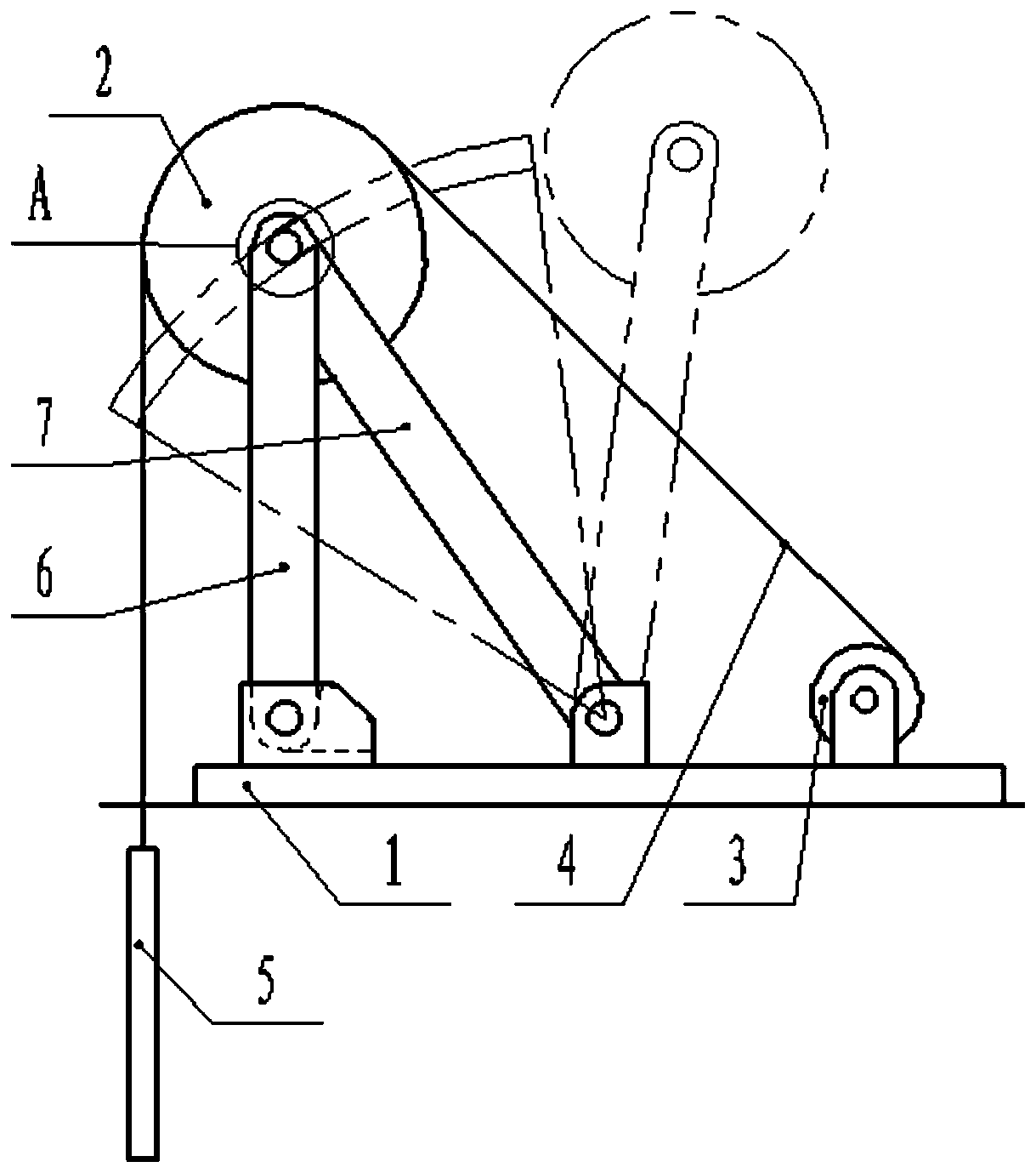
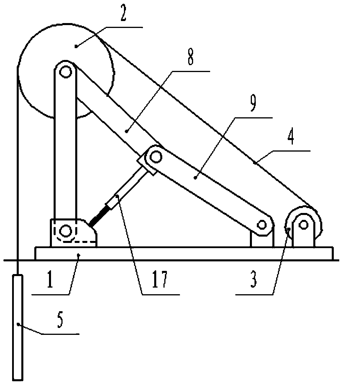
[0032] Such as figure 1 As shown, this embodiment includes a base 1, a support, a guide wheel 2, a reel 3, a wire rope 4, an oil well pump 5, a motor (not shown in the figure) and an intelligent variable frequency controller (not shown in the figure) for controlling the motor out), the bracket is fixedly installed on the base 1, the guide wheel 2 is installed on the top of the bracket, the reel 3 and the motor are fixedly installed on the base 1, the reel 3 rotates under the drive of the motor, and one end of the wire rope 4 is wound on the reel 3, the other end is connected with the oil pump 5 after bypassing the upper side of the guide wheel 2. The above is a common structure in the existing lifting type oil pumping unit, and will not be repeated here.

[0033] In the prior art, the wear of the wire rope 4 mainly occurs at the reel 3, and there are two specific reasons ...


PUM


Abstract

The invention belongs to the technical field of oil extraction devices for an oil field, and particularly relates to an intelligent oil sucking machine. The intelligent oil sucking machine comprises abase, a support frame, a guide wheel, a winding drum, a steel wire rope, an oil sucking pump and a motor, wherein a spiral groove for accommodating the steel wire rope is formed in the outer wall ofthe winding drum; the winding drum is in inclined arrangement; an included acute angle alpha formed between the axial line of the winding drum and the steel wire rope and the helix angle beta of the spiral groove meet a relationship that alpha=90 degree - beta; the winding drum structurally comprises a drum body, a driving shaft, a threaded support shaft and a shaft support frame; one end of the drum body is connected with a driving shaft through a spline; and the other end of the drum body is connected with the threaded support shaft through transmission screw threads. The intelligent oil sucking machine has the advantages that through the arrangement of the spiral groove with great thread pitches, the steel wire rope to be wound on the winding drum can be effectively prevented from beingin contact with the steel wire rope wound on the winding drum, so that the abrasion of the steel wire rope is reduced.

Description

technical field [0001] The invention belongs to the field of oil recovery devices in oil fields, and in particular relates to an intelligent pumping unit. Background technique [0002] As an important oil production equipment, the pumping unit has long been widely used in oil field production all over the world, and the oil production efficiency of the pumping unit oil production system is mainly determined by the pump. At present, most of the pumping units widely used are beam pumping units. Due to the limitation of the ground pumping mechanism, the stroke of this pumping unit is relatively short, which leads to the problem of low oil production efficiency. In order to improve oil recovery efficiency, technicians have developed a lifting pumping unit based on an intelligent control system. This pumping unit uses a motor-driven reel as a power source, and pulls the plunger of the downhole oil pump through a steel wire rope. Oil pumping, compared with the prior art, this win...

Claims


Application Information

Patent Timeline
IPC IPC(8): E21B43/00F04B47/02
CPCE21B43/121F04B47/02
Inventor 徐海英
Owner 华运隆腾机械制造有限公司
Why Eureka
Try Eureka