Grain rotary discharging type drying device

A drying device and grain technology, applied in the direction of drying, drying machine, drying solid materials, etc., can solve the problems of insufficient drying of grain and poor drying effect, and achieve simple structure, easy popularization and application, The effect of increasing the drying area

Inactive Publication Date: 2020-05-19
杨文耀
View PDF5 Cites 1 Cited by
  • Summary
  • Abstract
  • Description
  • Claims
  • Application Information

AI Technical Summary

Problems solved by technology

[0004] The existing grain dryer accumulates grains in the drying chamber, so that

Method used


Image

  • Grain rotary discharging type drying device
  • Grain rotary discharging type drying device
  • Grain rotary discharging type drying device

Examples


Example Embodiment

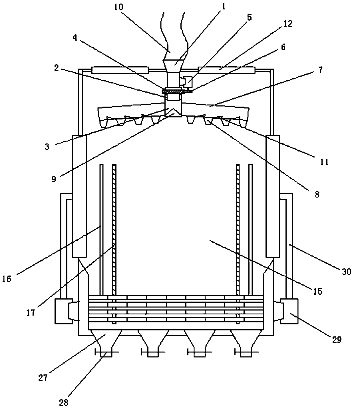
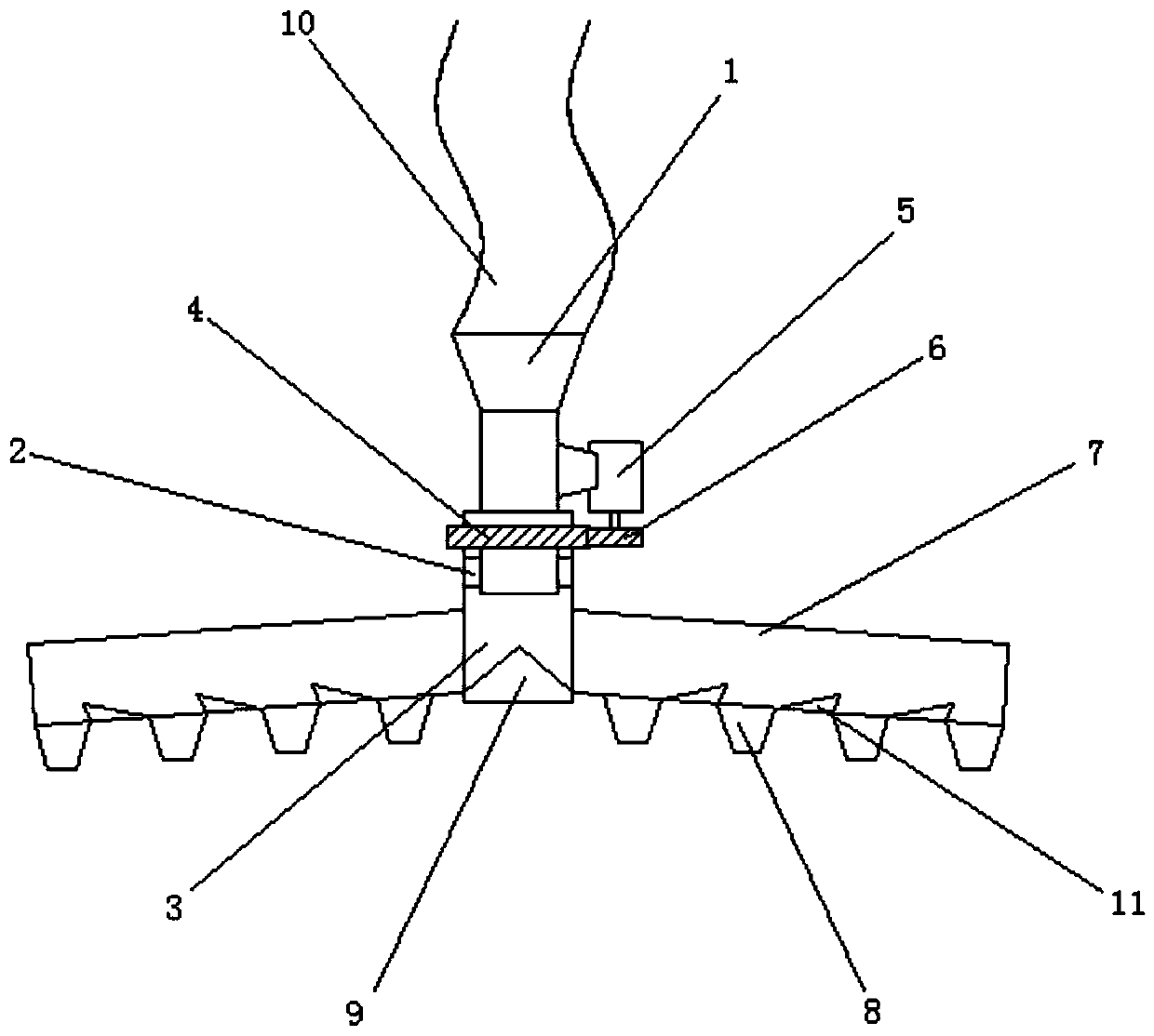
[0030] Example 1: Such as Figure 1-6 As shown, a grain rotary feeding type drying device includes a feeding hopper 1 and a drying bin 15. The feeding hopper 1 is located at the top of the drying bin 15, and the grain to be processed is introduced inward through the feeding hopper A bearing 2 is fixedly installed on the outside of the bottom of the feed hopper 1, the bottom of the feed hopper 1 is rotatably connected to a drum 3 through the bearing 2, and the bottom of the drum 3 is sealed;

[0031] A first motor 5 is fixedly installed on the side wall of the hopper 1, a first gear 6 is fixedly connected to the bottom of the first motor 5, a ring gear 4 is fixedly connected to the top of the outer wall of the drum 3, and The first gear 6 meshes with the ring gear 4; the first motor drives the gear to rotate, and the mesh with the ring gear can drive the drum to rotate;

[0032] A feeding tube 7 is fixedly installed on both sides of the rotating drum 3, and a plurality of feeding op...

Example Embodiment

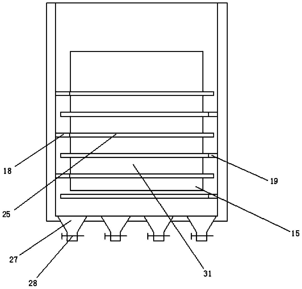
[0042] Example 2: Such as Figure 1-7 As shown, a grain rotary unloading drying device includes a feeding hopper 1 and a drying bin 15. The feeding hopper 1 is located at the top of the drying bin 15, and the grain to be processed is introduced inward through the feeding hopper. A bearing 2 is fixedly installed on the outside of the bottom of the feed hopper 1, the bottom of the feed hopper 1 is rotatably connected to a drum 3 through the bearing 2, and the bottom of the drum 3 is sealed;

[0043] A first motor 5 is fixedly installed on the side wall of the hopper 1, a first gear 6 is fixedly connected to the bottom of the first motor 5, a ring gear 4 is fixedly connected to the top of the outer wall of the drum 3, and The first gear 6 meshes with the ring gear 4; the first motor drives the gear to rotate, and the mesh with the ring gear can drive the drum to rotate;

[0044] A feeding tube 7 is fixedly installed on both sides of the rotating drum 3, and a plurality of feeding ope...


PUM


Abstract

The invention discloses a grain rotary discharging type drying device. The grain rotary discharging type drying device comprises a feed hopper and a drying bin, wherein the feed hopper is positioned at the top of the drying bin, a bearing is fixedly arranged on the outer side of the bottom of the feed hopper, a rotary drum is rotatably connected to the bottom of the feed hopper through the bearing, discharging pipes are fixedly arranged on two sides of the rotary drum, two groups of rails and two groups of toothed rails are arranged on two side walls of two sides of an inner cavity of the drying bin, three groups of first lifting frames and second lifting frames are separately movably connected to the rails on the two side walls, two groups of third motors are fixedly arranged on the rearsides of each group of first lifting frame and second lifting frame, one side of each third motor is fixedly connected with a second gear, and a plurality of groups of bearing plates are horizontallyarranged on the inner side walls of the first lifting frames and the second lifting frames; and the bottom of the drying bin is fixedly provided with a plurality of discharging hoppers. Grains can bedistributed on all the bearing plates layer by layer, the drying area is increased, and the drying efficiency is improved.

Description

Technical field: [0001] The invention relates to the field of grain processing, in particular to a grain rotary cutting type drying device. Background technique: [0002] Before storing grains such as rice and wheat, it is necessary to dry the grains. The usual method is to expose the grains. This drying method is inefficient and is easily affected by the weather and geographical environment. Many farmers expose the grains to the sun. There are also potential safety hazards along the road. Now grain dryers are usually used instead of traditional grain drying methods. [0003] Grain dryers are mainly used for drying rice and wheat, and can also be used for drying rapeseeds and other crops with a slight improvement. The grain dryer is composed of main components such as coal stove, electric motor, axial fan and stacking frame. When the grain dryer is working, the motor drives the impeller of the axial fan to rotate at a high speed, so that the hot air generated by the combustion of...

Claims


Application Information

Patent Timeline
IPC IPC(8): F26B17/24F26B21/00F26B25/00
CPCF26B17/24F26B21/001F26B25/00
Inventor 杨文耀
Owner 杨文耀
Why Eureka
Try Eureka