Optical path correction method and device for baseline drift in glove box type online spectral analysis

A technology of baseline drift and spectral analysis, which is applied in the field of optical path correction of baseline drift in glove box online spectral analysis, can solve problems affecting the service life and performance indicators of measuring equipment, install operating components, etc., and achieve timeliness problems, optical path The effect of simple structure and easy maintenance

Inactive Publication Date: 2020-05-19
CHINA INSTITUTE OF ATOMIC ENERGY
View PDF11 Cites 0 Cited by
  • Summary
  • Abstract
  • Description
  • Claims
  • Application Information

AI Technical Summary

Problems solved by technology

Cannot fit too many operating parts inside it
At the same time, the environment of strong acid, strong radioactivity and negative pressure in the glove box will affect the service life and performance indicators of the measuring equipment, and the vulnerable parts must be placed outside the glove box

Method used


Image

  • Optical path correction method and device for baseline drift in glove box type online spectral analysis
  • Optical path correction method and device for baseline drift in glove box type online spectral analysis
  • Optical path correction method and device for baseline drift in glove box type online spectral analysis

Examples


Embodiment 1

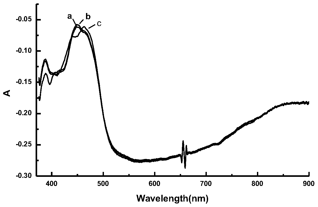
[0028] Turn on / off the light source: turn off the light source during the measurement, turn on the light source again after 30 minutes, and correct the baseline. refer to figure 2 , figure 2 It is a schematic diagram of the influence of turning on / off the light source on the baseline. In the figure, a is the initial baseline, b is after correction, and c is after the light source is turned on again. After the light source is turned on again, the baseline before 600nm drifts. Comparing the baselines before and after correction, it can be seen that the drift of the corrected baseline is eliminated.

Embodiment 2

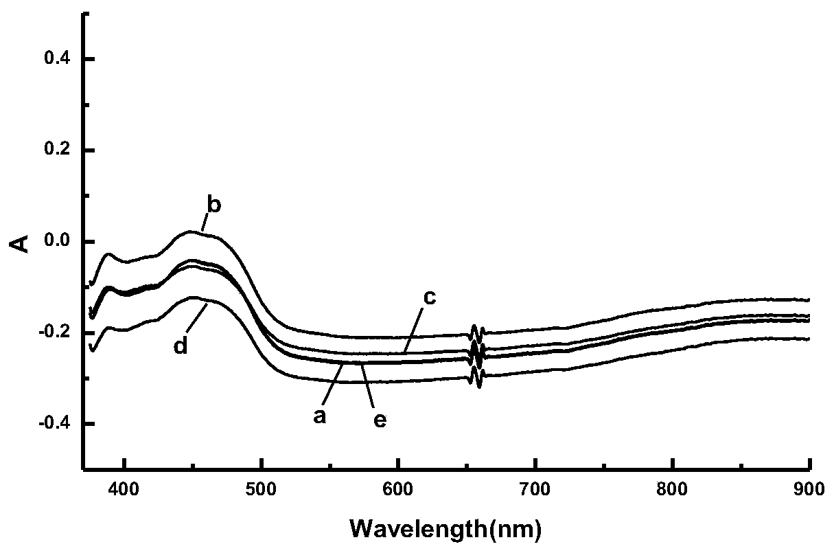
[0030] Change the intensity of the light source: the initial baseline is a; then block the light source with a light-transmitting film to reduce the intensity of the light source, and after reducing the intensity of the light source, the baseline becomes b; save the blank correction again to obtain the baseline c after light source occlusion correction. Because the occlusion is not removed, there is a slight difference between c and a, and they do not completely overlap. Then remove the occlusion, increase the light intensity, and the baseline becomes d; after saving blank correction again, the corrected baseline becomes e. refer to image 3 , image 3 It is a schematic diagram of correcting the influence of light source intensity changes on the baseline. In the figure, a is the initial spectrum; b is reducing the light intensity; c is correcting after reducing the light intensity; d is increasing the light intensity; e is correcting after increasing the light intensity . S...


PUM


Abstract

The invention provides an optical path correction method and device for baseline drift in glove box type online spectral analysis. The method comprises the steps that a measuring light path arranged in a glove box is connected in parallel on the basis of a closed online spectrum reference light path, the random switching between the measuring light path and the reference light path is achieved through a workstation, the reference light path is used for measuring blanks, the measuring light path is used for measuring samples online, and the online correction of baseline drift is achieved whilethe samples are measured. According to the optical path correction method and device for baseline drift in online spectral analysis, the online correction of the baseline drift is achieved while sample measurement is conducted, the timeliness problem of correction is solved, meanwhile, a sample light path does not need to be emptied and cleaned, and the continuity of online monitoring is guaranteed. In order to facilitate instrument maintenance and guarantee instrument performance, a required and designed correction optical path is simple in structure, easy to maintain and few in rotating component.

Description

technical field [0001] The invention belongs to the technical field of on-line quantitative analysis of spectra, in particular to an optical path correction method and device for baseline drift in glove box-type on-line spectral analysis. Background technique [0002] Online spectral analysis technology has many advantages: fast analysis speed, instant data acquisition, continuous and simultaneous measurement of multiple components, etc., so it is more and more widely used in process monitoring of industrial production. The timely and accurate analysis data it provides has played an irreplaceable role in stabilizing production and reducing labor costs. But the technology also has some problems that need to be solved. For example, after several hours of continuous operation of the analysis device, the state of the instrument will change. On the one hand, the intensity of the light source will change with changes in temperature, voltage, etc., resulting in a drift in the inte...

Claims


Application Information

Patent Timeline
Patent Type & Authority Applications(China)
IPC IPC(8): G01N21/27
CPCG01N21/274
Inventor 张丽华王玲刘焕良钱红娟李辉波范德军
Owner CHINA INSTITUTE OF ATOMIC ENERGY
Why Eureka
Try Eureka