Method and system for detecting crack propagation failure of thermal barrier coating

A thermal barrier coating and crack propagation technology, applied in the fields of instrumentation, electrical digital data processing, informatics, etc., can solve the problems of lack of quantitative analysis of crack phenomenon, difficulty in meeting accuracy requirements, hidden dangers of reliability in the use of TBC coated parts, etc. Achieve real-time detection and analysis capabilities, meet engineering accuracy, and use a wide range of environments.

Active Publication Date: 2020-05-19
苏州先机动力科技有限公司
View PDF2 Cites 8 Cited by
  • Summary
  • Abstract
  • Description
  • Claims
  • Application Information

AI Technical Summary

Problems solved by technology

The growth of the oxide layer inside the coating and the process of crack propagation are highly dependent on the local geometric configuration and deformation state on the microscopic scale, as well as the spatial fluctuation and temporal change of the material composition. Under complex working conditions , the failure location and service life of the TBC coating of the component are also random, which will inevitably bring great hidden dangers to the reliability of the TBC coating component
[0005] However, in some current models describing the crack formation and propagation inside thermal barrier coatings, either the basic fracture mechanism is missing, or the quantitative analysis of the randomness of crack phenomena is lacking, so it is difficult to implement reliability control at the component level. Accuracy requirements
Strictly speaking, the current cutting-edge TBC damage analysis methods do not yet have the ability to quantify the life of TBC-coated industrial equipment components

Method used


Image

  • Method and system for detecting crack propagation failure of thermal barrier coating
  • Method and system for detecting crack propagation failure of thermal barrier coating
  • Method and system for detecting crack propagation failure of thermal barrier coating

Examples


Embodiment

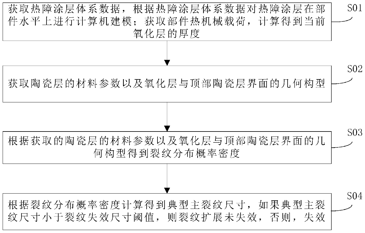
[0058] Such as figure 1 As shown, a detection method for crack propagation failure of a thermal barrier coating comprises the following steps:

[0059] S01: Acquire the data of the thermal barrier coating system, and conduct computer modeling of the thermal barrier coating at the component level according to the data of the thermal barrier coating system; obtain the thermomechanical load of the component, and calculate the thickness of the current oxide layer;

[0060] S02: Obtain the material parameters of the ceramic layer and the geometric configuration of the interface between the oxide layer and the top ceramic layer;

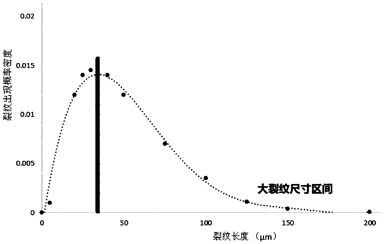
[0061] S03: Obtain the crack distribution probability density according to the obtained material parameters of the ceramic layer and the geometric configuration of the interface between the oxide layer and the top ceramic layer;

[0062] S04: The typical main crack size is calculated according to the crack distribution probability density. If the typical ...


PUM


Abstract

The invention discloses a method for detecting crack propagation failure of a thermal barrier coating, which comprises the following steps of: acquiring thermal barrier coating system data, and performing computer modeling on the thermal barrier coating on a part level according to the thermal barrier coating system data; obtaining the thermomechanical load of the part, and calculating to obtain the thickness of the current oxide layer; acquiring material parameters of the ceramic layer and a geometric configuration of an interface of the oxide layer and the top ceramic layer; obtaining the crack distribution probability density according to the obtained material parameters of the ceramic layer and the geometric configuration of the interface of the oxide layer and the top ceramic layer; and calculating according to the crack distribution probability density to obtain a typical main crack size, if the typical main crack size is smaller than a crack failure size threshold, determining that crack propagation does not fail, and otherwise, determining that failure occurs. Probability distribution of microstructure damage characteristics of the thermal barrier coating in the random useprocess is obtained through a statistical analysis method, various factors of TBC failure are covered, the current TBC damage condition can be accurately judged in real time, and the precision available for engineering is achieved.

Description

technical field [0001] The invention belongs to the technical field of detection of thermal barrier coatings, and in particular relates to a detection method and system for crack propagation failure of thermal barrier coatings. Background technique [0002] The thermal components of industrial gas turbines are key components directly related to safety. Based on the performance requirements of the equipment, these components generally have a surface thermal barrier coating (TBC). The TBC system is usually composed of the outermost ceramic layer, the bonding layer, and the intermediate Thermally grown oxide (TGO) grown over time. Common spraying methods for TBC include plasma atmospheric plasma spraying (APS). During the daily operation of gas turbines, the TGO layer gradually grows and thickens due to long-term exposure to high temperature environments, and under the action of internal stress in thermal cycles, microcracks continuously appear and expand at the interface betw...

Claims


Application Information

Patent Timeline
Patent Type & Authority Applications(China)
IPC IPC(8): G06F30/20G16C60/00G06F119/02
CPCG16C60/00Y02T50/60
Inventor 赵军陈滢邵诚卓
Owner 苏州先机动力科技有限公司
Why Eureka
Try Eureka