Composite and multi-station full-die-cutting ultrahigh-frequency tag antenna machining equipment and method

A processing equipment, ultra-high frequency technology, used in metal processing, record carriers used in machines, devices for coating liquids on surfaces, etc., and can solve problems such as antenna layer offset

Pending Publication Date: 2020-05-22
黄光伟
View PDF0 Cites 1 Cited by
  • Summary
  • Abstract
  • Description
  • Claims
  • Application Information

AI Technical Summary

Problems solved by technology

[0004] The purpose of the present invention is to provide a fully die-cut UHF electronic tag antenna and its processing equipment and processing technology, mainly to solve the problem in the above-mentioned prior art: how to avoid using the etching process to produce UHF electronic tags The problem of the chip binding point and the chip binding positioning point of the antenna, problem two: how to com

Method used


Image

  • Composite and multi-station full-die-cutting ultrahigh-frequency tag antenna machining equipment and method
  • Composite and multi-station full-die-cutting ultrahigh-frequency tag antenna machining equipment and method
  • Composite and multi-station full-die-cutting ultrahigh-frequency tag antenna machining equipment and method

Examples


specific Embodiment 2

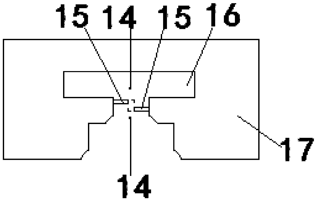
[0110] Specific embodiment 2, specific embodiment 2 is basically the same as present embodiment 1, the difference is: in the production step seven of the processing technology of the UHF electronic tag antenna of full die-cutting in specific embodiment 2, the first die-cutting The mechanism is a die-cutting machine that performs flat die-cutting and / or circular knife die-cutting on the chip binding point 15 and the chip binding positioning point 14 at the same time, that is to say, the first die-cutting mechanism completes the chip binding point 15, The flat die-cutting and / or circular knife die-cutting of the chip binding positioning point 14, for example, all of them are replaced by a flat die-cutting machine with a circular knife die-cutting machine is also a similar operation to perform a one-time flat die-cutting on the antenna layer to form The chip binding point 15 and the chip binding positioning point 14, that is to say, the die-cutting tool of the flat die-cutting mac...

specific Embodiment 3

[0114] The specific embodiment 3, the specific embodiment 3 is basically the same as the present embodiment 1, the difference is: in the production step seven of the processing technology of the full-die-cut UHF electronic tag antenna in the specific embodiment 3, the described method for The first die-cutting mechanism for die-cutting the chip binding positioning point 14 and the chip binding point 15 and the second die-cutting mechanism 10 for die-cutting the peripheral edge of the antenna body 17 are combined into a flat-press die-cutting machine or a circular knife die cutting machine.

[0115] That is to say, the first die-cutting mechanism and the second die-cutting mechanism 10 are merged into a flat die-cutting machine or a circular knife die-cutting machine, which can complete the flat die-cutting of the chip binding point 15 and the chip binding positioning point 14 at one time. Cutting and / or circular knife die-cutting and carrying out flat die-cutting and / or circul...

specific Embodiment 4

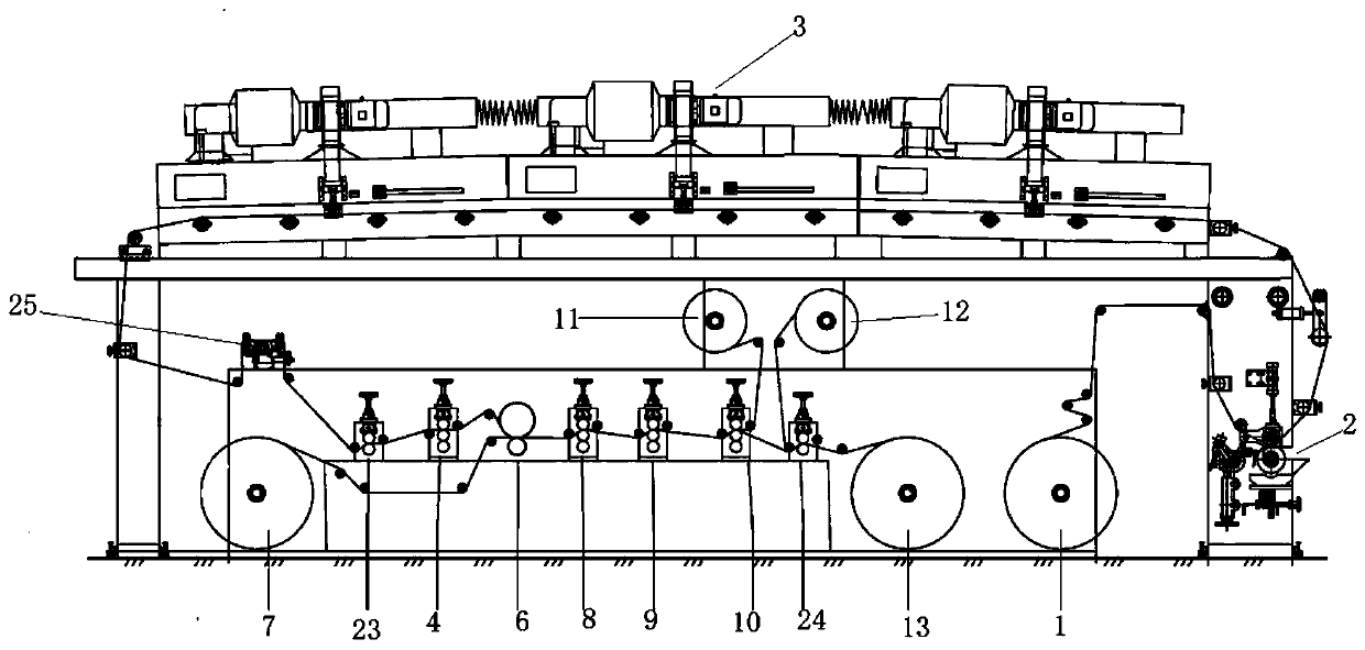
[0118] Specific embodiment 4, see Figure 5 , The specific embodiment 4 is basically the same as the present embodiment 1, the difference is: in the specific embodiment 4, there are two chip binding points, and the processing equipment also includes a second row of waste rewinding mechanism 26;

[0119]The first die-cutting mechanism is used to carry out one of the chip binding points, the redundant antennas on both sides of the antenna layer or the redundant antennas on both sides of the first base material layer and the antenna layer, and the redundant first base material layers on both sides. The first flat-press die-cutting machine of flat-press die-cutting or the first round-knife die-cutting machine 8 of circular knife die-cutting, and be used for carrying out flat-press die-cutting to another chip binding point 15 and chip binding positioning point 14 The second flat-press die-cutting machine for cutting or the second round-knife die-cutting machine 9 for round-knife di...


PUM


Abstract

The invention provides composite and multi-station full-die-cutting ultrahigh frequency tag antenna machining equipment and method, and relates to an ultrahigh frequency tag antenna. An antenna body is provided with a chip binding positioning point formed in a die cutting mode and a chip binding point formed in the die cutting mode. A second base material layer or a first base material layer and the second base material layer are pasted on one side of an antenna layer of the antenna body. The machining equipment is characterized by comprising a first die cutting mechanism, a second die cuttingmechanism and a traction mechanism. The machining equipment and method solve the problem of, in the prior art, 1, how to avoid the problem of using an etching process to produce a chip binding pointand a chip binding positioning point of an ultra-high frequency electronic tag antenna; 2, how to completely avoid the use of an etching process in the production process of the ultra-high frequency electronic tag antenna; 3, how to prevent the antenna layer from shifting during movement or driving in the machining process; and 4, how to help the antenna layer to move or drive better while maintaining the tension.

Description

technical field [0001] The invention relates to the technical field of electronic tags, in particular to a composite and multi-station full-die-cut UHF tag antenna processing equipment and method. Background technique [0002] At present, the chip binding point and chip binding positioning point of the UHF electronic tag antenna are still produced by etching process. The etching process requires chemical substances such as hydrochloric acid, which has a great impact on the environment. Therefore, how to avoid using the etching process to produce ultra-high frequency The chip binding point and chip binding positioning point of the high-frequency electronic tag antenna have become urgent problems to be solved. [0003] In addition, how to completely avoid the problem of using the etching process in the production process of the UHF electronic tag antenna, how to prevent the antenna layer from moving or shifting during transmission, and how to help the antenna layer move better...

Claims


Application Information

Patent Timeline
IPC IPC(8): B26D7/18B26D9/00B26F1/38B05C11/10B05C9/14B05C13/02B05D3/02G06K19/077
CPCB05C9/14B05C11/10B05C13/02B05D3/0254B26D7/18B26D9/00B26F1/38G06K19/07745
Inventor 黄光伟
Owner 黄光伟
Why Eureka
Try Eureka