Scrap iron recovery device for automobile part machining

A technology for auto parts and recycling devices, applied in metal processing equipment, metal processing machinery parts, manufacturing tools, etc., can solve the problems of inability to compress and recycle iron scraps, laborious, and occupy a large space, so as to improve the flattening efficiency, The effect of preventing rebound and reducing the occupied space

Inactive Publication Date: 2020-05-22
TIANMEN JINXINGDA AUTO PARTS
View PDF1 Cites 4 Cited by
  • Summary
  • Abstract
  • Description
  • Claims
  • Application Information

AI Technical Summary

Problems solved by technology

The invention achieves the effects of clean cleaning, fast cleaning speed, and simple operation, so that the cutting fluid can be washed away when the iron filings are recovered, but the device cannot compress and recover the iron filings, and the iron filings still occupy a large amount of space after cleaning. Separate processing, laborious

Method used


Image

  • Scrap iron recovery device for automobile part machining
  • Scrap iron recovery device for automobile part machining
  • Scrap iron recovery device for automobile part machining

Examples


Embodiment 1

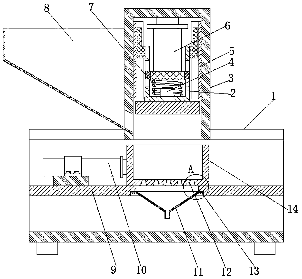
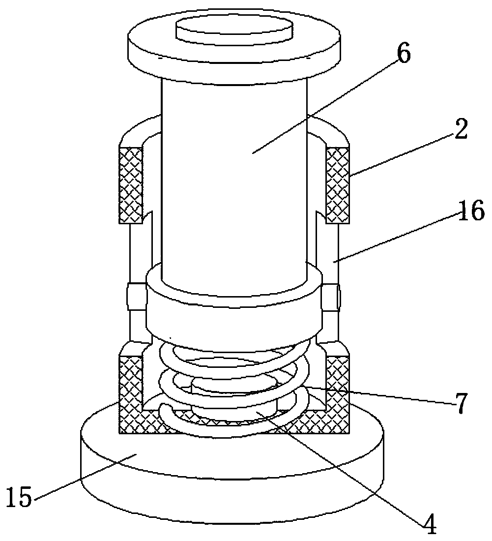
[0025] refer to Figure 1-3 , an iron chip recovery device for auto parts processing, comprising a base 1 with an upward opening in a C-shaped steel structure, a fixed box 3 with an opening downwards in a rectangular parallelepiped barrel-shaped structure snapped into the middle of the top of the base 1, and the top of the fixed box 3 The inner wall is provided with a hydraulic ejector rod 6, and the bottom of the main pipe of the hydraulic ejector rod 6 is fixed with a compression spring 7. plate 15, and the side of the fixed box 3 is provided with a feed port, the side of the feed port is provided with a material frame 8, the middle of the base 1 is provided with a partition 9, and the middle of the lower surface of the partition 9 has a ladder installation hole 13. A waste collection frame 14 is fixed on the upper surface of the partition 9 close to the top of the step installation hole 13, and the bottom of the waste collection frame 14 is provided with leaking holes 12 di...

Embodiment 2

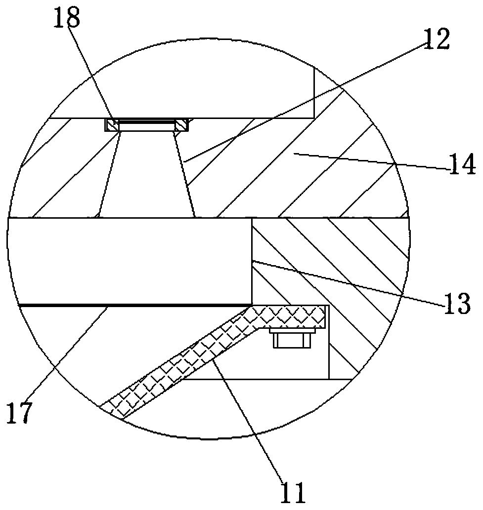
[0032] refer to figure 1 and image 3 , an iron chip recovery device for processing auto parts. Compared with Embodiment 1, this embodiment also includes the hole diameters at the upper and lower ends of the leakage hole 12 at the bottom of the waste collection frame 14. The aperture is smaller than the aperture near the bottom, and the top of the leakage hole 12 is clamped with a filter ring 18 .

[0033] Working principle: When in use, the cutting fluid mixed in the waste chips can be quickly discharged when compressed.


PUM


Abstract

The invention discloses a scrap iron recovery device for automobile part machining. The device comprises a base with an upward opening and of a C-shaped steel structure, a fixing box with a downward opening and of a cuboid barrel-shaped structure is clamped to the middle of the top end of the base, a hydraulic ejector rod is arranged on the inner wall of the top end of the fixing box, and a compression spring is fixed to the bottom of a main pipe of the hydraulic ejector rod; a pressing barrel with an upward opening and of a barrel-shaped structure is arranged at the bottom end of the compression spring, a pressing disc is arranged at the bottom of the pressing barrel, a feeding opening is formed in the side face of the fixing box, and a material gathering frame is arranged on the side face of the feeding opening; and a partition plate is arranged in the middle of the base, a stepped mounting hole is formed in the middle of the lower surface of the partition plate, and a waste collecting frame is fixed above the upper surface, close to the stepped mounting hole, of the partition plate. According to the scrap iron recovery device, the hydraulic ejector rod can be used for driving the pressing disc to press fluffy scraps so that not only can mingled greasy dirt be removed, but also the occupied space of the waste collecting frame is reduced.

Description

technical field [0001] The invention relates to the technical field of iron filings recovery, in particular to an iron filings recycling device for processing auto parts. Background technique [0002] During the processing of auto parts, there will be a lot of iron filings. These iron filings will make the desktop very messy and may affect the work. In addition, cutting fluid will be used in the cutting process. The iron filings should be Recycling needs to clean the cutting fluid. The current iron chip recovery device has the disadvantages of unclean cleaning, slow cleaning speed, and complicated operation. Therefore, it is urgent to develop a cutting process for auto parts manufacturing that is clean, fast, and easy to operate. Use scrap recycling device. [0003] After searching, the Chinese patent number is CN201621271264.1, which includes a bottom plate, a left frame, a support rod, a cleaning box, a liquid outlet pipe, a valve, a mesh plate, a first bearing seat, a fi...

Claims


Application Information

Patent Timeline
Patent Type & Authority Applications(China)
IPC IPC(8): B30B9/32B30B9/06B30B9/26B23Q11/00
CPCB23Q11/0067B23Q11/0075B30B9/06B30B9/26B30B9/32
Inventor 裴少军
Owner TIANMEN JINXINGDA AUTO PARTS
Why Eureka
Try Eureka