Vacuum wiredrawing furnace for optical fiber manufacturing

A drawing furnace and optical fiber preform technology, which is applied in the field of optical fiber manufacturing, can solve the problem of inability to draw micro-structured optical fibers with qualified geometric dimensions, and achieve the effects of good geometric size consistency, no impurity pollution, and good strength.

Pending Publication Date: 2020-05-22
TONGDING INTERCONNECTION INFORMATION CO LTD
View PDF0 Cites 3 Cited by
  • Summary
  • Abstract
  • Description
  • Claims
  • Application Information

AI Technical Summary

Problems solved by technology

[0005] The purpose of the present invention is to solve the problem that the existing optical fiber drawing furnace cannot draw the microstructured optical fiber with qualified geometric dimensions, and to provide a vacuum drawing furnace for optical fiber manufacturing. The vacuu

Method used


Image

  • Vacuum wiredrawing furnace for optical fiber manufacturing
  • Vacuum wiredrawing furnace for optical fiber manufacturing
  • Vacuum wiredrawing furnace for optical fiber manufacturing

Examples


Embodiment Construction

[0028] The present invention will be further described below in conjunction with drawings and embodiments.

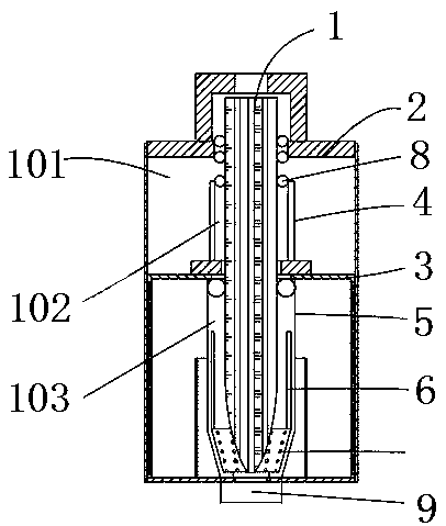
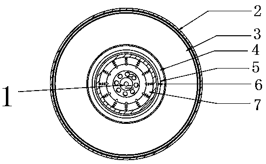
[0029] see figure 1 and figure 2 A vacuum drawing furnace for optical fiber manufacturing is shown, including an optical fiber preform 1, a drawing furnace chamber cover 2, a drawing furnace body 3, a second vacuum zone cover 4, a core heating zone cover 5, and a heating coil 6 and graphite parts 7; the drawing furnace chamber cover 2 is located outside the drawing furnace body 3; the second vacuum zone cover 4 is vertically arranged on the upper part of the drawing furnace body 3, and is located between the drawing furnace chamber cover 2 and the drawing furnace body 3; In the area between the furnace body 3; the core heating zone outer cover 5 is arranged in the drawing furnace body 3, and is arranged from top to bottom along the top of the drawing furnace body 3 to the bottom of the drawing furnace body 3; wherein, the A first vacuum zone 101 is formed between the...


PUM


Abstract

The invention provides a vacuum wiredrawing furnace for optical fiber manufacturing. The vacuum wiredrawing furnace comprises an optical fiber preform, a wiredrawing furnace chamber outer cover, a wiredrawing furnace body, a second vacuum area outer cover, a core heating area outer cover, a heating coil and a graphite part, wherein a first vacuum area is defined by the wiredrawing furnace chamberouter cover, the second vacuum area outer cover and the wiredrawing furnace body; a second vacuum area is defined between the second vacuum area outer cover and the wiredrawing furnace body; a core heating area is defined between the core heating area outer cover and the wiredrawing furnace body; the optical fiber preform sequentially penetrates through the wiredrawing furnace chamber outer cover,the second vacuum area and the wiredrawing furnace body and extends into the bottom of the core heating area in the wiredrawing furnace; the graphite part is arranged at the bottom of the core heating area, and a circle of the heating coil is arranged on the upper side of the graphite part in the circumferential direction of the optical fiber preform. According to the vacuum wiredrawing furnace,the structural design is more optimized, impurity pollution is avoided, the cost is lower and the consistency of optical fiber parameters is better when common optical fibers are drawn, and the capability of drawing photonic crystal optical fibers with a complex structure is achieved.

Description

technical field [0001] The invention relates to the field of optical fiber manufacturing, in particular to a vacuum drawing furnace for optical fiber manufacturing. Background technique [0002] Optical fiber drawing refers to melting and drawing an optical fiber preform of a certain diameter online through a drawing equipment into an optical fiber with a certain geometric requirement. The heating equipment for melting optical fiber preform (commonly called fiber drawing furnace) is one of the core equipment of the fiber drawing process, which can directly affect many important technical parameters of the fiber, such as geometric parameters, fiber attenuation, fiber strength, polarization mode dispersion Wait. Traditional optical fiber drawing furnace can draw single-mode optical fiber (G.652, G.653, G.654, G.655, G.657, etc.), multi-mode optical fiber (OM1, OM2, OM3, OM4, etc.). [0003] At present, the traditional drawing furnaces in the optical fiber industry are DC res...

Claims


Application Information

Patent Timeline
IPC IPC(8): C03B37/029
CPCC03B37/029
Inventor 沈小平杨志杰吴志华朱坤郭圣峰
Owner TONGDING INTERCONNECTION INFORMATION CO LTD
Why Eureka
Try Eureka