

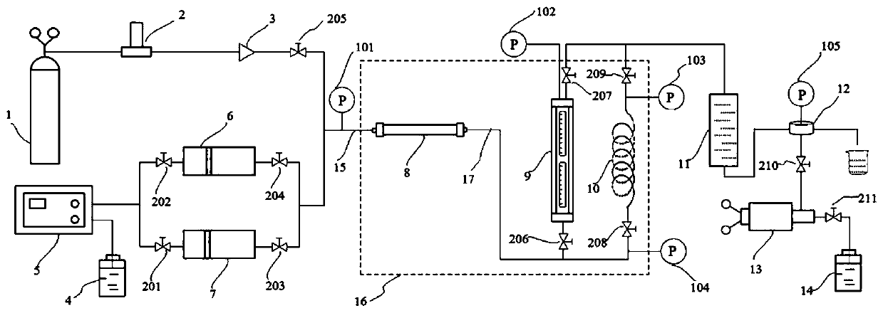
Combined test device for high-temperature and high-pressure foam in-situ generation and evaluation and use method
An in-situ generation and testing device technology, applied in the direction of measuring devices, suspension and porous material analysis, instruments, etc., can solve the problem of not being able to control the gas-liquid volume ratio, not being able to know the stability and flow of the foam, and not being able to shear the foam and other issues to achieve accurate, convenient, stability and fluidity, perfect generation and stability, and real and accurate simulation conditions
- Summary
- Abstract
- Description
- Claims
- Application Information
AI Technical Summary
Problems solved by technology
Method used
Image

Examples
Embodiment 1
[0070] The foaming agent is 1.0 wt% sodium lauryl polyoxyethylene ether sulfate dispersion, the temperature of the temperature control box 16 is set at 50° C., and the back pressure of the back pressure valve 12 is set at 2.0 MPa. Table 1 shows the physical parameters of the sand filling pipe 8 in this embodiment, and Table 2 shows the half-life and fluidity of the foam in this embodiment.
[0071] Table 1 Physical parameters of sand filling pipe in Example 1
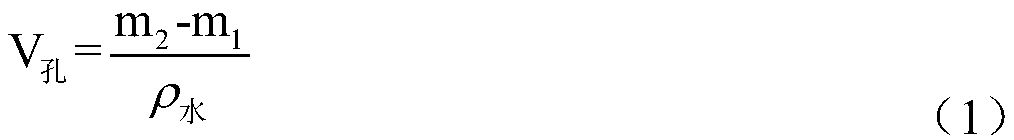
[0072] Quartz grain number dry weight m 1 / g
Wet weight m 2 / g
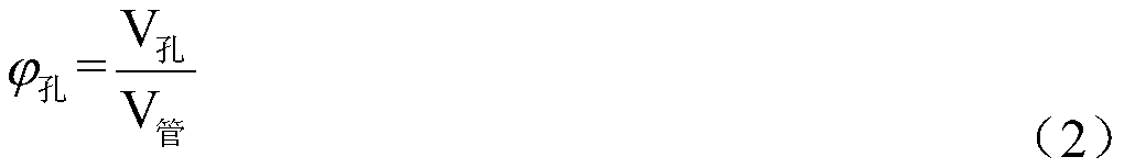
Pore volume / mL Porosity / % Permeability / μm 2
40-60 18.32 18.51 0.19 47.5 8.76
[0073] Table 2 Foam half-life and fluidity when the total gas-liquid flow rate is 0.30mL / min
[0074]
Embodiment 2
[0076] Foaming agent is 0.05wt% sodium 2-ethylhexyl succinate sulfonate / 1.0wt% nano-SiO 2 For the particle dispersion, the temperature of the temperature control box 16 is set at 50° C., and the back pressure of the back pressure valve 12 is set at 4.0 MPa. Table 3 shows the physical parameters of the sand filling pipe 8 in this embodiment, and Table 4 shows the half-life and fluidity of the foam in this embodiment.
[0077] Table 3 Physical parameters of sand filling pipes in Example 1
[0078] Quartz grain number dry weight m 1 / g
Wet weight m 2 / g
Pore volume / mL Porosity / % Permeability / μm 2
60-80 18.33 18.53 0.20 46.3 8.21
[0079] Table 4 Foam half-life and fluidity when the total gas-liquid flow rate is 0.30mL / min
[0080]
Embodiment 3
[0082] The foaming agent is 0.05wt% monododecyl phthalate sodium salt / 0.008wt% welan gum dispersion, the temperature of the temperature control box 16 is set to 50°C, and the backpressure valve 12 is set to a backpressure of 4.0MPa . Table 5 shows the physical parameters of the sand filling pipe 8 in this embodiment, and Table 6 shows the half-life and fluidity of the foam in this embodiment.
[0083] Table 5 Physical parameters of sand filling pipes in Example 2
[0084] Quartz grain number dry weight m 1 / g
Wet weight m 2 / g
Pore volume / mL Porosity / % Permeability / μm 2
80-100 18.35 18.56 0.21 46.0 7.82
[0085] Table 6 The fluidity and stability of foam when the total gas-liquid flow rate is 0.30mL / min
[0086]
[0087]
PUM
| Property | Measurement | Unit |
|---|---|---|
| length | aaaaa | aaaaa |
| length | aaaaa | aaaaa |
Abstract
Description
Claims
Application Information