Light guide plate and image display device

A light guide plate and grating technology, applied in optics, light guides, optical components, etc., can solve problems such as narrow viewing angles, and achieve the effect of improving brightness and visual recognition

Active Publication Date: 2020-05-22
HITACHI-LG DATA STORAGE
View PDF9 Cites 2 Cited by
  • Summary
  • Abstract
  • Description
  • Claims
  • Application Information

AI Technical Summary

Problems solved by technology

On the other hand, in contrast to the above-mentioned concavo-convex diffraction gratings that can achieve a large viewing angle due to the duplication of light in two-dimensional directions in the light guide plate, they only provide the function of one-dimensional duplication, so they have the characteristics of a relatively narrow viewing angle

Method used


Image

  • Light guide plate and image display device
  • Light guide plate and image display device
  • Light guide plate and image display device

Examples


Embodiment 1

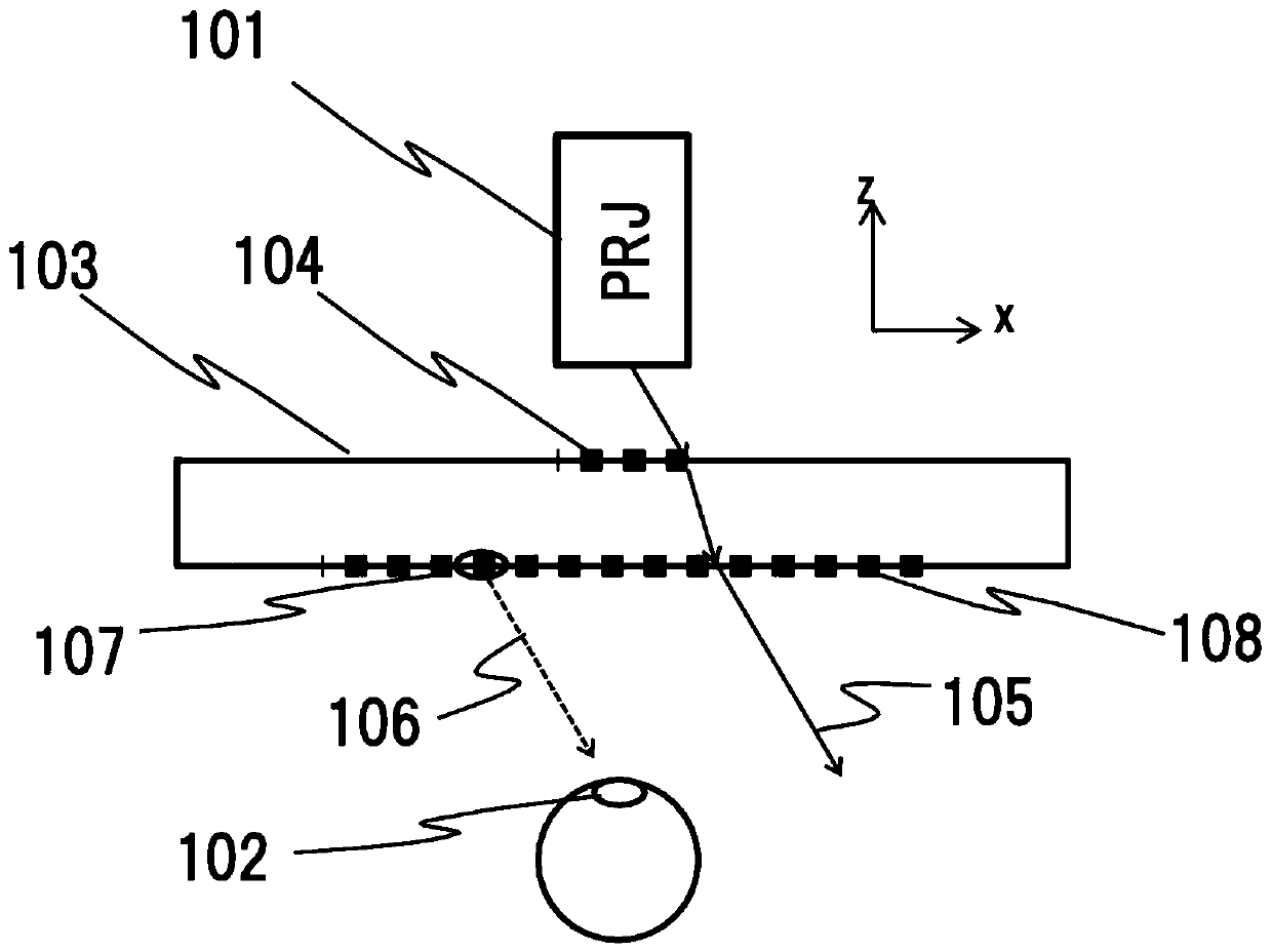
[0143] Figure 8 The structure of the image display element of this embodiment is shown. Hereinafter, the present invention will be described using the angle θ formed by the period P of the surface unevenness pattern and the X-axis as a parameter for determining the wave vector of the diffraction grating. In the figure, an incident diffraction grating 104 (period P, angle θi=0), an output diffraction grating 108 (period P, angle θo) and an intermediate diffraction grating 300 (period Pm, angle θm) are formed on the light guide plate 103 . The incident diffraction grating 104 is composed of a linear grating elongated in the x direction, and the period of the pattern is P. The periodic direction of the pattern of the incident diffraction grating 104 is the y direction. The output diffraction grating 108 is a linear grating whose pattern period is also P, and the angle formed between each grating and the x-axis is θo. In the case of the light guide plate described in Patent Do...

Embodiment 2

[0168] Figure 15 It is a schematic diagram showing the whole process of forming the light guide plate of the present example utilizing the mass production process of the optical disk, and is a diagram schematically showing the manufacturing process of the image display element of the example. First, if Figure 15 As in step 1 shown in (a), prepare the master pattern 1501 of the incident diffraction grating and intermediate diffraction grating and the master pattern 1502 of the outgoing diffraction grating by EB (electron beam) drawing method or the like. The master mold 1502 for emitting the diffraction grating was transferred to a Ni stamper in a manner suitable for the injection molding process, and used.

[0169] Then, if Figure 15 As in step 2 shown in (b), the substrate 1503 on which the emission diffraction grating 108 is formed on the surface is produced by injection molding using a plastic material using the master mold 1502 for the emission diffraction grating. A...

Embodiment 3

[0182] Figure 17 It is a schematic diagram showing the structure of the image display device 1700 of this embodiment. The light with image information emitted from the projector 101 reaches the pupil 102 of the user through the functions of the light guide plates 103R, 103G, and 103B of B, G, and R, thereby realizing augmented reality. The light guide plates 103R, 103G, and 103B of B, G, and R are Figure 15 Optical device 1506 is shown, forming a diffraction grating whose pitch and depth are optimized for each color.

[0183] In the drawing, an image display device 1700 is composed of an optical device 1506 , a projector 101 as an image forming unit, and a display image control unit (not shown). Here, the optical device 1506 integrates R, G, and B light guide plates 103R, 103G, and 103B for color display. In addition, as an image forming unit, for example, an image forming device composed of a reflective or transmissive spatial light modulator, a light source, and a lens,...


PUM

PropertyMeasurementUnit
thicknessaaaaaaaaaa
wavelengthaaaaaaaaaa

Abstract

According to the present invention, the present invention, in a light guide plate (image display element) having a diffraction grating and an image display device using the light guide plate, the brightness of the image recognized by the user is improved, and the visual confirmation is improved. The light guide plate including an incident diffraction grating which diffracts incident imaging light,an exit diffraction grating through which the imaging light goes out, and an intermediate diffraction grating existing in optical paths from the incident diffraction grating to the exit diffraction grating. In this light guide plate, a periodic linear corrugated pattern is formed as the incident diffraction grating, and when an imaginary line is established that passes through an incident point of imaging light onto the incident diffraction grating and is parallel with a periodic direction of the corrugated pattern, the intermediate diffraction grating has a first region on one side of the imaginary line and a second region on another side of the imaginary line.

Description

technical field [0001] The present invention relates to a small and lightweight light guide plate and an image display device capable of displaying augmented reality, which combine a light guide plate and a diffraction element. Background technique [0002] In the augmented reality image display device, the user can not only view the projected image but also view the surroundings at the same time. The projected image can overlap with the real world perceived by the user. Other applications of these displays include wearable devices such as video games and glasses. By wearing glasses or a goggle-shaped image display device in which a translucent light guide plate and a projector are integrated, the user can visually confirm an image supplied from the projector superimposed on the real world. [0003] Such image display devices are described in "Patent Document 1" to "Patent Document 3". In these patent documents, the light guide plate is composed of a plurality of concavo-...

Claims


Application Information

Patent Timeline
Patent Type & Authority Applications(China)
IPC IPC(8): G02B27/01
CPCG02B27/0101G02B27/0172G02B6/34G02B2027/0118G02B2027/0178G02B6/0016G02B6/0088
Inventor 峰邑浩行安斋由美子
Owner HITACHI-LG DATA STORAGE
Why Eureka
Try Eureka