Energy-saving heating device and method of use

A technology of heating device and economizer, applied in the field of HVAC, can solve the problems of low utilization rate of condensed water, difficult hydraulic balance adjustment, high maintenance cost and operating cost, and achieves avoiding slow temperature rise, reasonable structure, and reduced maintenance. cost effect

Active Publication Date: 2021-12-14
XINJIANG UYGUR AUTONOMOUS REGION NO 3 MACHINE TOOL WORKS
View PDF0 Cites 0 Cited by
  • Summary
  • Abstract
  • Description
  • Claims
  • Application Information

AI Technical Summary

Problems solved by technology

[0004] The present invention provides an energy-saving heating device and its use method, which overcomes the deficiencies of the above-mentioned prior art, and can effectively solve the problems of difficult adjustment of hydraulic balance, low utilization rate of condensed water, high maintenance cost and high operating cost in the existing heating system. question

Method used


Image

  • Energy-saving heating device and method of use
  • Energy-saving heating device and method of use
  • Energy-saving heating device and method of use

Examples


Embodiment 1

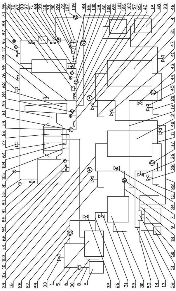
[0030] Embodiment one: as attached figure 1 , 2 , 3, the energy-saving heating device includes a boiler 54, a primary economizer 64, a secondary economizer 62, a chimney 63, a condenser 65, a primary side primary water pump 60, a primary side secondary water pump 61, and a condensed water tank 1. The first network water tank 48, the second network water tank 106 and the primary side water supply pump 100. The condenser 65 is a hollow tube with a thick middle and thin sides and is horizontally arranged. The exhaust port of the boiler 54 and the air inlet of the chimney 63 are condensed The condensers 65 are fixedly connected together, and the inner side of the middle part of the condenser 65 is fixedly installed with a primary economizer 64, the air inlet of the primary economizer 64 corresponds to the exhaust port of the boiler 54, and the exhaust port of the primary economizer 64 corresponds to the chimney The air inlet of 63 is corresponding, and the first-level water inlet...

Embodiment 2

[0045] Embodiment two: as attached figure 1 , 2 As shown, a method of using the above-mentioned energy-saving device includes the following steps:

[0046] a. water injection;

[0047] b. run;

[0048] c. Condensed water collection: During operation, the condensed water in the condenser 65 flows through the condensed water collecting pipe 103 and flows into the condensed water tank 1. When half of the condensed water in the condensed water tank 1 is collected, close the first circulation valve 31 and The second circulation valve 32, open the third circulation valve 33 and the dosing pump 6, add sodium hydroxide solution in the condensed water tank 1 for 1 minute to 3 minutes; close the first circulation valve 31, the third circulation valve 33 and the dosing pump Pump 6, open the second circulation valve 32 and the self-circulation pump 27, and circulate the neutralized condensed water in the condensed water tank 1 for 3 minutes to 7 minutes; close the second circulation va...


PUM


Abstract

The present invention relates to the field of heating and ventilation technology, and is an energy-saving heating device and its use method. The former includes a boiler, a primary energy-saving device, a secondary energy-saving device, a chimney, a condenser, a primary-side primary water pump, a primary-side secondary water pump, Condensed water tank, primary net water tank, secondary net water tank and primary side make-up water pump; the latter includes the following steps: water injection; operation; condensate water collection; data collection and analysis; adjustment; water replenishment. The structure of the invention is reasonable and compact. By installing a water treatment device, strong corrosion of the pipes in the condensed water can be avoided. By installing a primary side water supply pump, the condensed water can be reinjected into the pipe network to supplement the water loss in the pipe network. Reduce the water consumption during the operation of the heating system and reduce maintenance costs. By setting the pressure equalizing valve, the heat supplied by the boiler can be quickly increased, avoiding the situation of slow temperature rise and large heat loss in the entire pipe network, and reducing high-temperature flue gas. The impact of emissions on the environment and reduce operating costs.

Description

technical field [0001] The invention relates to the technical field of heating and ventilation, and relates to an energy-saving heating device and a using method. Background technique [0002] Under the background of the country's energy saving and emission reduction, the existing exhaust heat of boilers is recovered to reduce the exhaust gas temperature below the dew point temperature of the flue gas. The latent heat released when a large amount of water vapor condenses. At the same time, the condensate has a certain absorption effect on harmful gases such as carbon dioxide, nitrogen oxides, and sulfur oxides in the flue gas. Therefore, it can improve energy utilization and reduce environmental pollution caused by exhaust smoke. [0003] However, there are the following problems in the recovered boiler flue gas condensate: first, the boiler flue gas condensate is acidic after the harmful gas dissolves in the water, so that the condensate will cause strong corrosion to the ...

Claims


Application Information

Patent Timeline
Patent Type & Authority Patents(China)
IPC IPC(8): F24D3/10F24D19/10C02F9/04
CPCF24D3/1058F24D19/1015F24D19/1012C02F9/00C02F1/66C02F1/001C02F1/20C02F1/00C02F2001/007C02F5/00
Inventor 陆琦高长乐姚占伟陈进江陈国军刘麟赵伟
Owner XINJIANG UYGUR AUTONOMOUS REGION NO 3 MACHINE TOOL WORKS
Why Eureka
Try Eureka