
Switched capacitor converter system based on lithium battery SOC application

A switched capacitor and converter technology, applied in the field of switched capacitor converter systems, can solve problems such as poor transient response, simultaneous conduction, power tube breakdown, etc.

Active Publication Date: 2020-05-26
ANYKA (GUANGZHOU) MICROELECTRONICS TECH CO LTD
View PDF7 Cites 0 Cited by
  • Summary
  • Abstract
  • Description
  • Claims
  • Application Information

AI Technical Summary

Problems solved by technology

[0005] 2. When the power tubes in the topology are switched, there is a possibility that they will be turned on at the same time, which will easily cause a large current loss in an instant, and there is also the possibility of power tube breakdown.
In order to improve efficiency and stability, a dead zone control to avoid false conduction is introduced to make up for the shortcomings of fixed and non-adjustable delays in non-overlapping circuits
[0006] 3. Since the power supply input is a lithium battery, the battery voltage range varies from 2.9V to 4.2V. If only a single-gain topology is used, the efficiency will be very low under part of the power supply voltage.
[0008] 5. The loop control of the switched capacitor converter controlled by a single clock signal is relatively complicated. When the compensation capacitor and resistor are introduced to provide loop compensation, at a certain switching frequency, the transient response is poor, there is large ripple, and the efficiency is low. For SOC applications, such as digital core, the voltage sensitivity is strong, small ripple is required, and efficiency and transient response need to be improved as much as possible

Method used


Image

  • Switched capacitor converter system based on lithium battery SOC application
  • Switched capacitor converter system based on lithium battery SOC application
  • Switched capacitor converter system based on lithium battery SOC application

Examples


Embodiment Construction

[0032] The specific embodiment of the present invention will be further described below in conjunction with accompanying drawing:

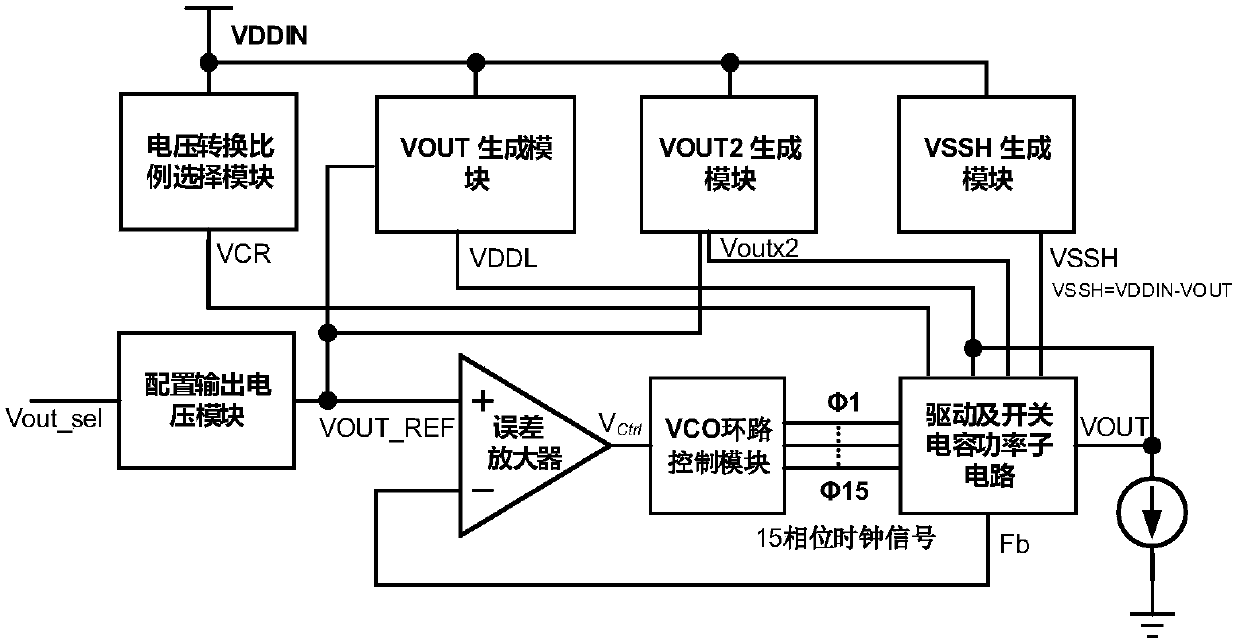
[0033] refer to figure 1 , the present invention is a switched capacitor converter system based on lithium battery SOC applications, including a voltage conversion ratio selection module, a VOUT generation module, a VOUT2 generation module, a VSSH generation module, a configuration output voltage module, an error amplifier, a VCO loop control module and The drive and switched capacitor power subcircuit, the output terminal of the voltage conversion ratio selection module is connected to the first input terminal of the drive and switched capacitor power subcircuit, the output terminal of the VOUT generating module is connected to the drive and switched capacitor power subcircuit The second input terminal is connected, the output terminal of the VOUT2 generation module is connected with the third input terminal of the driving and switched capacitor ...


PUM


Abstract

The invention discloses a switched capacitor converter system based on lithium battery SOC application. The system comprises a voltage conversion proportion selection module, a VOUT generation module,a VOUT2 generation module, a VSSH generation module, a configuration output voltage module, an error amplifier, a VCO loop control module and a driving and switched capacitor power sub-circuit. According to the invention, wide-range voltage input is achieved, the dual-mode gain topology can be efficiently configured, the mistakenly-conducted dead zone circuit control situation is effectively avoided, losses are greatly reduced, and stable digital configurable voltage output is completed. In addition, the VOUT generation module can ensure the stability during output starting and transient change by introducing an LDO with a specific mismatch operational amplifier, and the defect that a control loop cannot be regulated and controlled is overcome. The switched capacitor converter system canbe widely applied to converter structures.

Description

technical field [0001] The invention relates to the technical field of electronic circuits, in particular to a switched capacitor converter system based on the application of lithium battery SOC. Background technique [0002] Lithium batteries are the main source of energy for mobile devices. The voltage range of commonly used lithium batteries is 2.9V to 4.2V, usually 3.6V. However, the power supply voltage of processors and SOC applications often needs to be as low as about 1V. In order to To solve the problem of voltage difference, a fully integrated voltage regulator on-chip is extremely important. Due to the low integration of the key element inductance in the inductive switching voltage converter, in the CMOS process, it is difficult to use the existing process to manufacture a larger inductor to meet its needs. [0003] However, in the design of the switched capacitor converter system for SOC applications based on lithium batteries, there are the following problems: ...

Claims


Application Information

Patent Timeline
IPC IPC(8): H02M3/07
CPCH02M3/073H02M3/077
Inventor 杨建新胡胜发
Owner ANYKA (GUANGZHOU) MICROELECTRONICS TECH CO LTD
Learn More