Flexible direct-current cable with cooling function

A flexible DC and functional technology, applied in the direction of power cables including optical transmission components, power cables, insulated cables, etc., can solve problems such as impact, loss of national economy and residents' lives, and accelerated thermal aging of cable insulation.

Inactive Publication Date: 2020-05-29
浙江万马股份有限公司
View PDF6 Cites 2 Cited by
  • Summary
  • Abstract
  • Description
  • Claims
  • Application Information

AI Technical Summary

Problems solved by technology

[0004] The purpose of the present invention is to overcome the existing common ±10kV flexible DC cable in the operation process of the current scheme. When the circuit is overloaded, the conductor heating will increase sharply, which greatly exceeds the long-term allowable operating temperature of the conductor (90°C). If the thermal aging speed of the cable insulation is reduced, the service life of the cable and the long-term stable operation of the line will be greatly reduced, which will bring immeasurable losses and impacts on the national economy and residents' lives. 10kV Flexible DC Cable

Method used


Image

  • Flexible direct-current cable with cooling function

Examples


Embodiment 1

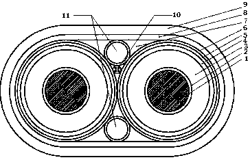
[0017] A flexible DC cable with self-cooling function (see attached figure 1 ), including a cable core, a cooling duct 11 and a temperature-measuring optical fiber unit 10, the cable core includes a conductor 1, the conductor is covered with a conductor shielding layer 2, and the outside of the conductor shielding layer is covered with an insulating layer 3, and the insulation The outer side of the layer is covered with an insulating shielding layer 4, the outer side of the insulating shielding layer is covered with a semi-conductive buffer layer 5, the outer side of the semi-conductive buffer layer is covered with a metal shielding layer 6, the cable core, cooling pipe and the temperature measuring optical fiber unit are all wrapped in the tape layer 8, the space inside the tape layer is filled with a cable filling rope 7, and the outside of the tape layer is covered with an outer sheath 9; The temperature measuring optical fiber unit is connected with a temperature monitorin...

Embodiment 2

[0020] This embodiment is basically the same as Embodiment 1, except that in this embodiment, the outer sheath is a polyethylene sheath, and the outside of the outer sheath is covered with asphalt-coated fiber hemp rope. This embodiment increases the anti-corrosion performance of the cable. The high-density polyethylene outer sheath material has a compact molecular structure and has very strong corrosion resistance. At the same time, the fiber hemp rope coated with asphalt is also a corrosion-resistant material. The cable insulation Under the protection of the two-layer structure, the wire core can still operate normally in the environment of soaking in seawater for a long time, providing guarantee for the long-term stable operation of the DC cable line.

Embodiment 3

[0022] This embodiment is basically the same as Embodiment 1, except that in this embodiment, the outer sheath is a polyethylene sheath of self-sensing temperature masterbatch. The self-sensing temperature color masterbatch polyethylene sheath can be used as an auxiliary. When there is still an ultra-high temperature in the case of automatic cooling, or when there is a problem with self-cooling, the temperature drop can be avoided through the self-sensing temperature color masterbatch polyethylene sheath. further up.


PUM


Abstract

The invention relates to a flexible direct-current cable with a cooling function. With the flexible direct-current cable with the cooling function adopted, defects in the prior art are overcome. According to the technical schemes, the flexible direct-current cable with the cooling function comprises cable cores, cooling pipelines and a temperature measurement optical fiber unit. Each cable core comprises a conductor; a conductor shielding layer wraps the conductor; the outer side of the conductor shielding layer is coated with an insulating layer; the outer side of the insulating layer is coated with an insulating shielding layer; the outer side of the insulation shielding layer is wrapped by a semi-conductive buffer layer; and the outer side of the semi-conductive buffer layer is wrappedby a metal shielding layer. The cable cores, the cooling pipelines and the temperature measurement optical fiber unit are wrapped by a wrapping tape layer; a gap in the inner side of the wrapping tapelayer is filled with a cable filling rope; and the outer side of the wrapping tape layer is wrapped by an outer sheath; the temperature measurement optical fiber unit is connected with a temperaturemonitoring system; the cooling pipelines are connected with a tap water pipeline; the running of tap water is controlled through an electromagnetic valve; and the control signal of the electromagneticvalve is provided by the temperature monitoring system.

Description

technical field [0001] The invention relates to a flexible DC cable, in particular to a ±10kV flexible DC cable with its own cooling function. Background technique [0002] For a long time, because AC power generation is relatively simple and does not require rectification, and AC transmission is convenient for voltage transformation and high-voltage transmission to reduce losses, AC transmission has always been the main method of power transmission. However, with the development of the power system, the increase of transmission capacity and distance, the stability of AC transmission and the short-circuit capacity under cut-off faults have become increasingly complex. In the development of new technologies such as high-power thyristors and automatic control of DC transmission Today, DC transmission technology has become possible and developed rapidly, and has been widely used all over the world. Compared with AC transmission, DC transmission has the following advantages: (1...

Claims


Application Information

Patent Timeline
Patent Type & Authority Applications(China)
IPC IPC(8): H01B9/02H01B9/00H01B7/42H01B7/32H01B7/28G01K11/32
CPCH01B9/02H01B9/027H01B9/005H01B7/423H01B7/42H01B7/324H01B7/2806G01K11/32
Inventor 余德平李金堂刘焕新孟益标梁增显
Owner 浙江万马股份有限公司
Why Eureka
Try Eureka